AFBR-5803AQZ Ver la hoja de datos (PDF) - Avago Technologies
Número de pieza
componentes Descripción
Lista de partido
AFBR-5803AQZ
Avago Technologies

AFBR-5803AQZ Datasheet PDF : 16 Pages
| |||
Regulatory Compliance Table
Feature
Electrostatic Discharge (ESD)
to the Electrical Pins
Electrostatic Discharge (ESD)
to the Duplex SC Receptacle
Test Method
MIL-STD-883
Method 3015.4
Variation of
IEC 801-2
Electromagnetic
Interference (EMI)
Immunity
FCC Class B
CENELEC CEN55022
Class B (CISPR 22B)
VCCI Class 2
Variation of
IEC 61000-4-3
Performance
Meets Class 1 (<1999 Volts)
Withstand up to 1500 V applied between electrical pins.
Typically withstand at least 25 kV without damage when the Duplex
SC Connector Receptacle is contacted by a Human Body Model
probe.
Transceivers typically provide a 13 dB margin (with duplex SC
receptacle) or a 9 dB margin (with duplex ST receptacles ) to the
noted standard limits. However, it should be noted that final margin
depends on the customer’s board and chassis design.
Typically show no measurable effect from a 10 V/m field swept from
10 to 450 MHz applied to the transceiver when mounted to a circuit
card without a chassis enclosure.
Electromagnetic Interference (EMI)
Most equipment designs utilizing these high speed trans
ceivers from Avago Technologies will be required to meet
the requirements of FCC in the United States, CENELEC
EN55022 (CISPR 22) in Europe and VCCI in Japan.
In all well-designed chassis, two 0.5” holes for ST con-
nectors to protrude through will provide 4.6 dB more
shielding than one 1.2” duplex SC rectangular cutout.
Thus, in a well-designed chassis, the duplex ST 1 x 9
transceiver emissions will be identical to the duplex SC 1
x 9 transceiver emissions.
Immunity
Equipment utilizing these transceivers will be subject to
radio-frequency electromagnetic fields in some environ-
ments. These transceivers have a high immunity to such
fields.
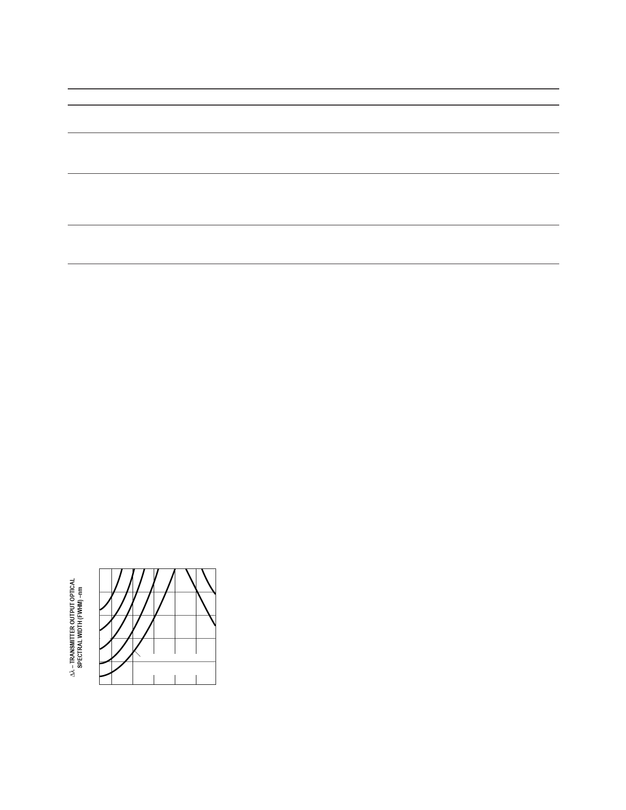
200
180 1.5
160 2.0
140 2.5
120 3.0
3.5
3.0
3.5
tr/f – TRANSMITTER
OUTPUT OPTICAL
RISE/FALL TIMES – ns
AFBR-5103 FDDI
TRANSMITTER
TEST RESULTS
OF λC, ∆λ AND
tr/f ARE CORRELATED
AND COMPLY WITH
THE ALLOWED
SPECTRAL WIDTH
AS A FUNCTION OF
CENTER WAVELENGTH
FOR VARIOUS RISE
AND FALL TIMES.
100 1200 1300 1320 1340 1360 1380
λC – TRANSMITTER OUTPUT OPTICAL
CENTER WAVELENGTH –nm
Figure 9. Transmitter Output Optical Spectral Width (FWHM) vs. Transmitter
Output Optical Center Wavelength and Rise/Fall Times.
For additional information regarding EMI, susceptibility,
ESD and conducted noise testing procedures and results
on the 1 x 9 Transceiver family, please refer to Applica-
tions Note 1075, Testing and Measuring Electromagnetic
Compatibility Performance of the AFBR-510X/520X Fiber
Optic Transceivers.
Transceiver Reliability and Performance Qualification
Data
The 1 x 9 transceivers have passed Avago Technologies
reliability and performance qualification testing and are
undergoing ongoing quality monitoring. Details are avail
able from your Avago Technologies sales representative.
Accessory Duplex SC Connectored Cable Assemblies
Avago Technologies recommends for optimal coupling
the use of flexible-body duplex SC connectored cable.
Accessory Duplex ST Connectored Cable Assemblies
Avago Technologies recommends the use of Duplex
Push-Pull connectored cable for the most repeatable
optical power coupling performance.
Share Link: