AIC1580CN Ver la hoja de datos (PDF) - Analog Intergrations
Número de pieza
componentes Descripción
Lista de partido
AIC1580CN Datasheet PDF : 8 Pages
| |||
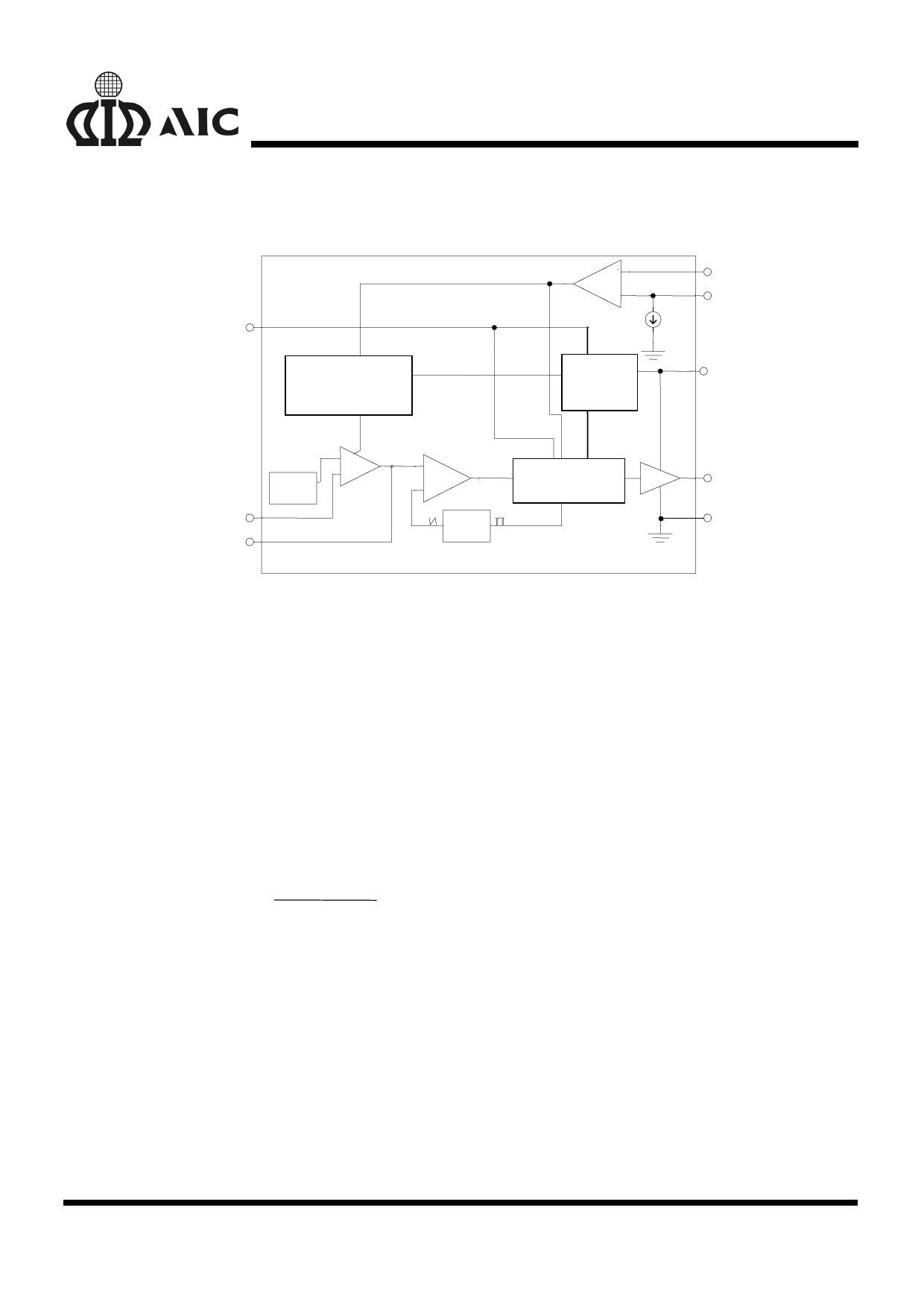
BLOCK DIAGRAM
AIC1580/L
SD
Built-In Soft Start
Over Current
-
+
200µA
PHASE
OCSET
Power-On
Reset
VCC
FB
COMP
+
PWM Comparator
-
+
Gate Control
REF
Error AMP
-
Oscilator
UGATE
GND
PIN DESCRIPTIONS
PIN 1: OCSET - Current limit sense pin. Connect
a resistor ROCSET from this pin to
the drain of the external
MOSFET. ROCSET, an internal
200µA current source (IOCSET),
and the external MOSFET on-
resistance (RDS(ON)) jointly set
the overcurrent trip point
according to the following
equation:
IPEAK
=
IOCSET × ROCSET
RDS(ON)
If FB pin voltage is sensed to be
below 50% of the internal
voltage reference VDAC, the
overcurrent comparator cycles
the soft-start function.
PIN 2: SD
- Shutdown pin. Connect this pin
to ground for shutdown.
PIN 3: COMP - External compensation pin. This
pin is connected to error
amplifier output and PWM
comparator. A RC network is
connected to FB pin to
compensate the voltage-control
feedback loop of the converter.
PIN 4: FB -
The error amplifier inverting
input pin. The FB pin and COMP
pin are used to compensate the
voltage-control feedback loop.
PIN 5: GND- Ground pin.
PIN 6: PHASE-
Overcurrent detection pin.
Connect the PHASE pin to
source of the external N-
MOSFET. This pin detects the
voltage drop across the
MOSFET RDS(ON) for overcurrent
protection.
PIN 7: UGATE- External MOSFET gate drive pin.
Connect this pin to gate of the
external MOSFET.
PIN 8: VCC
-The chip power supply pin.
Recommended supply voltage is
12V.
6
Share Link: 