PIC16C925 Ver la hoja de datos (PDF) - Microchip Technology
Número de pieza
componentes Descripción
Lista de partido
PIC16C925 Datasheet PDF : 182 Pages
| |||
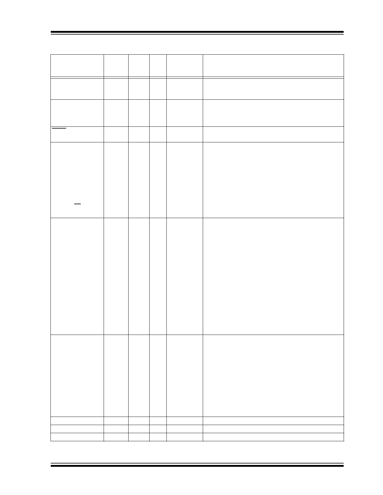
PIC16C925/926
TABLE 1-2: PIC16C925/926 PINOUT DESCRIPTION
Pin Name
OSC1/CLKIN
OSC2/CLKOUT
PLCC,
CLCC
Pin#
24
TQFP Pin
Pin# Type
14
I
25
15
O
MCLR/VPP
RA0/AN0
RA1/AN1
RA2/AN2
RA3/AN3/VREF
RA4/T0CKI
RA5/AN4/SS
2
57
I/P
5
60
I/O
6
61
I/O
8
63
I/O
9
64
I/O
10
1
I/O
11
2
I/O
RB0/INT
RB1
RB2
RB3
RB4
RB5
RB6
RB7
13
4
I/O
12
3
I/O
4
59
I/O
3
58
I/O
68
56
I/O
67
55
I/O
65
53
I/O
66
54
I/O
RC0/T1OSO/T1CKI
26
16
I/O
RC1/T1OSI
RC2/CCP1
27
17
I/O
28
18
I/O
RC3/SCK/SCL
14
5
I/O
RC4/SDI/SDA
15
6
I/O
RC5/SDO
C1
C2
COM0
Legend: I = input
— = Not used
16
7
I/O
17
8
P
18
9
P
63
51
L
O = output
TTL = TTL input
Buffer
Type
Description
ST/CMOS
—
Oscillator crystal input or external clock source input. This
buffer is a Schmitt Trigger input when configured in RC
oscillator mode and a CMOS input otherwise.
Oscillator crystal output. Connects to crystal or resonator in
crystal oscillator mode. In RC mode, OSC2 pin outputs
CLKOUT, which has 1/4 the frequency of OSC1 and denotes
the instruction cycle rate.
ST
Master Clear (Reset) input or programming voltage input. This
pin is an active low RESET to the device.
PORTA is a bi-directional I/O port.
TTL
RA0 can also be Analog input0.
TTL
RA1 can also be Analog input1.
TTL
RA2 can also be Analog input2.
TTL
RA3 can also be Analog input3 or A/D Voltage
Reference.
ST
RA4 can also be the clock input to the Timer0
timer/counter. Output is open drain type.
TTL
RA5 can be the slave select for the synchronous serial port
or Analog input4.
PORTB is a bi-directional I/O port. PORTB can be software
programmed for internal weak pull-ups on all inputs.
TTL/ST
RB0 can also be the external interrupt pin. This buffer is a
Schmitt Trigger input when configured as an
external interrupt.
TTL
TTL
TTL
TTL
Interrupt-on-change pin.
TTL
Interrupt-on-change pin.
TTL/ST
Interrupt-on-change pin. Serial programming clock. This
buffer is a Schmitt Trigger input when used in Serial
Programming mode.
TTL/ST
Interrupt-on-change pin. Serial programming data. This
buffer is a Schmitt Trigger input when used in Serial
Programming mode.
PORTC is a bi-directional I/O port.
ST
RC0 can also be the Timer1 oscillator output or Timer1
clock input.
ST
RC1 can also be the Timer1 oscillator input.
ST
RC2 can also be the Capture1 input/Compare1
output/PWM1 output.
ST
RC3 can also be the synchronous serial clock input/
output for both SPI and I2C modes.
ST
RC4 can also be the SPI Data In (SPI mode) or
data I/O (I2C mode).
ST
RC5 can also be the SPI Data Out (SPI mode).
LCD Voltage Generation.
LCD Voltage Generation.
Common Driver0.
P = power
L = LCD Driver
ST = Schmitt Trigger input
2001 Microchip Technology Inc.
Preliminary
DS39544A-page 7
Share Link: 