XE5620G Ver la hoja de datos (PDF) - Xecom
Número de pieza
componentes Descripción
Lista de partido
XE5620G Datasheet PDF : 19 Pages
| |||
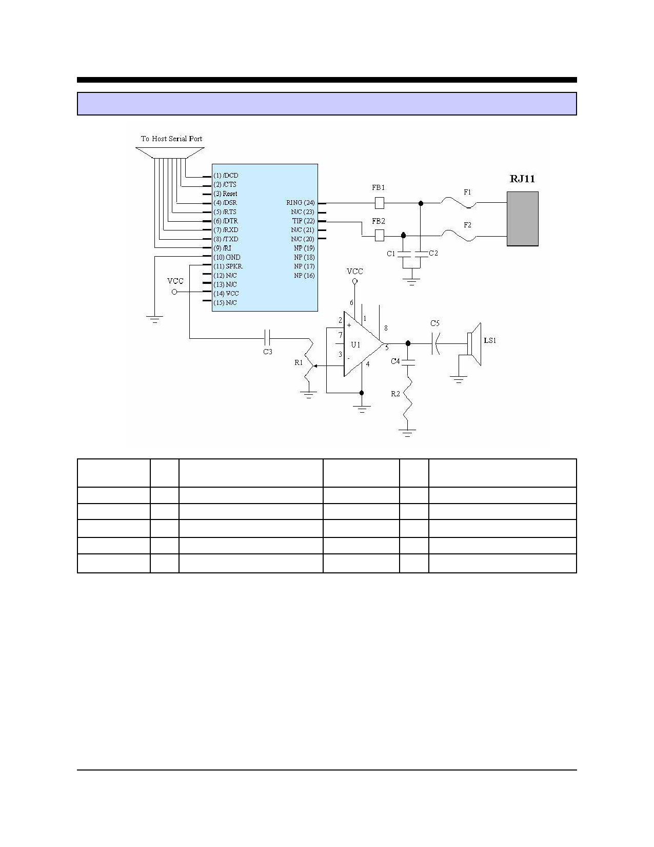
XE5620G Typical Connection Diagram
XE5620G
Parts List for XE5620G Typical Connection Diagram
Reference
Designation Qty Description
Reference
Designation Qty Description
C1, C2
2 Cap. 470 pfd 2600V
U1
1 National Semi LM386
C3, C4
2 Cap. 0.1 ufd 20% 16V
LS1
1 Speaker, 8 Ohms
C5
1 Cap. 100 ufd 20% 10V
R1
1 Potentiometer, 10K
FB1, FB2
2 Ferrite, TDK ACB2012L-120 R2
1 Resistor, 10 Ohms 20 %
F1, F2
2 PTC, TR600-150
Notes:
1 FB1 and FB2 are ferrite beads which may be required for EMI filtering in your system. Without these
components you may experience unintended radiation when the telephone cable is attached. We recommend
selecting components such as the TDK ACB2012L-120 which provide a minimum of 100 ohms of impedance
at frequencies above 100 MHz.
2. C1 and C2 are high-voltage capacitors which may be required for EMI filtering in your system. Without these
components you may experience unintended radiation when the telephone cable is attached to your system. We
recommend selecting components such as the Panasonic ECKDRS471. This 470 pfd, 3000 volt capacitor will
direct the high frequency harmonics to the system ground. These capacitors must be rated at a minimum of 1500
volts to maintain the isolation required by FCC Part 68 Rules.
3. F1 and F2 are positive thermal coefficient (PTC) devices which protect the modem form excessive current
flow. These devices are required for your system to pass UL60950. Fuses may be used in place of the PTC’s
XECOM
(7)
XE5620G
Share Link: 