RH5RI251B Ver la hoja de datos (PDF) - RICOH Co.,Ltd.
Número de pieza
componentes Descripción
Lista de partido
RH5RI251B Datasheet PDF : 24 Pages
| |||
RH5RI
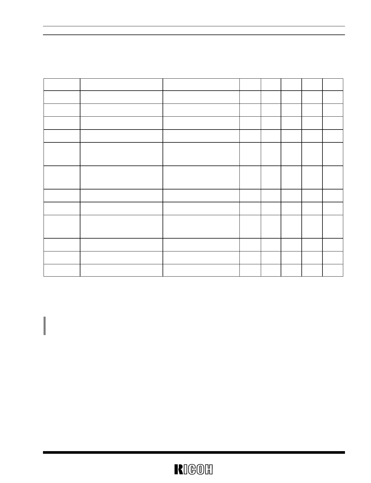
ELECTRICAL CHARACTERISTICS
• RH5RI301B
Symbol
VOUT
VIN
Vstart
Vhold
Item
Output Voltage
Input Voltage
Start-up Voltage
Hold-on Voltage
Conditions
IOUT=1mA,VIN:0→2V
IOUT=1mA,VIN:2→0V
IIN1
Input Current 1
To be measured at VIN
at no load
IIN2
Input Current 2
To be measured at VIN
VIN=3.5V
ILX
ILXleak
Lx Switching Current
Lx Leakage Current
VLX=0.4V
VLX=6V,VIN=3.5V
fosc
Maximum Oscillator
Frequency
Maxdty
η
VLXlim
Oscillator Duty Cycle
Efficiency
VLX Voltage Limit
on (VLX “L” ) side
Lx Switch On
MIN.
TYP.
MAX.
VOUT=3.0V
Unit Note
2.925 3.000 3.075 V
8
V
0.8 0.9
V
0.7
V
4
8
µA
2
5
µA
60
mA
0.5 µA
80 100 120 kHz
65
75 85
70
80
0.65 0.8 1.0
%
%
V Note
Unless otherwise provided, VIN=1.8V, Vss=0V, IOUT=10mA, Topt=25˚C, and use External Circuit of Typical
Application (FIG. 1).
(Note)
ILX is gradually increased by the external inductor after Lx Switch is turned ON. In accordance with the increase of ILX, VLX is also increased.
When VLX reaches VLXlim, Lx Switch is turned OFF by Lx Switch Protection Circuit. The time period from the time at which VLX reaches VLXlim to
the time at which Lx Switch is turned OFF is about 3µs.
5
Share Link: 