FS6261-01 Ver la hoja de datos (PDF) - AMI Semiconductor
Número de pieza
componentes Descripción
Lista de partido
FS6261-01 Datasheet PDF : 17 Pages
| |||
X T
)6
0RWKHUERDUG &ORFN *HQHUDWRU ,&
January 2000
Compared to the profile limits the modulation slew rate is
relatively slow between the limits, allowing the down-
stream PLL a chance to reduce the tracking skew. The
ability of the downstream PLL to catch up is determined
by the loop transfer function phase angle.
Spread spectrum clocking can be shown to have a negli-
gible effect on cycle-to-cycle jitter performance. Any in-
crease in jitter is less than 1ps when δ<1% and
fm<50kHz. Careful design of downstream PLLs can en-
sure that tracking skew is minimized. To have less than
100ps of tracking skew, a downstream PLL should have
a loop bandwidth greater than 1MHz, and a phase angle
less than 0.1°.
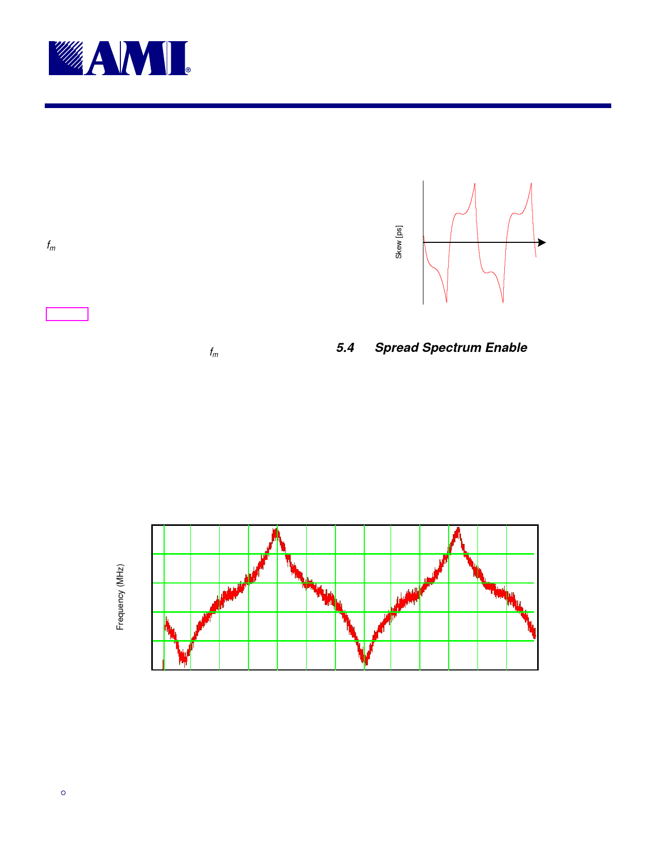
Figure 7 shows the tracking skew of a downstream PLL
with a loop bandwidth of 1.5MHz and a phase angle of
0.26° following a non-linear profile-modulated 100MHz
input clock with a δ=-0.5% and an fm=31.2kHz.
Figure 7: PLL Tracking Skew
PLL Tracking Skew
100
80
60
40
20
0
20
40
60
80
100
Time [us]
5.4 Spread Spectrum Enable
The active-low LVTTL SS_EN# input pin enables spread
spectrum modulation of the CPU and PCI clocks. When
SS_EN# is a logic-high, the spread spectrum modulation
of these clocks is disabled. If SS_EN# is a logic-low,
spread spectrum modulation is enabled.
A pull-up on this pin disables spread spectrum modula-
tion by default.
Figure 8: Actual Modulation Profile
100
99.9
99.8
99.7
99.6
99.5
0
5
10
15
20
25
30
35
40
45
50
55
60
65
1/fm (µs)
,62
7
1.31.00
Share Link: 