OZ6812 Ver la hoja de datos (PDF) - O2Micro International
Número de pieza
componentes Descripción
Lista de partido
OZ6812 Datasheet PDF : 13 Pages
| |||
OZ6812
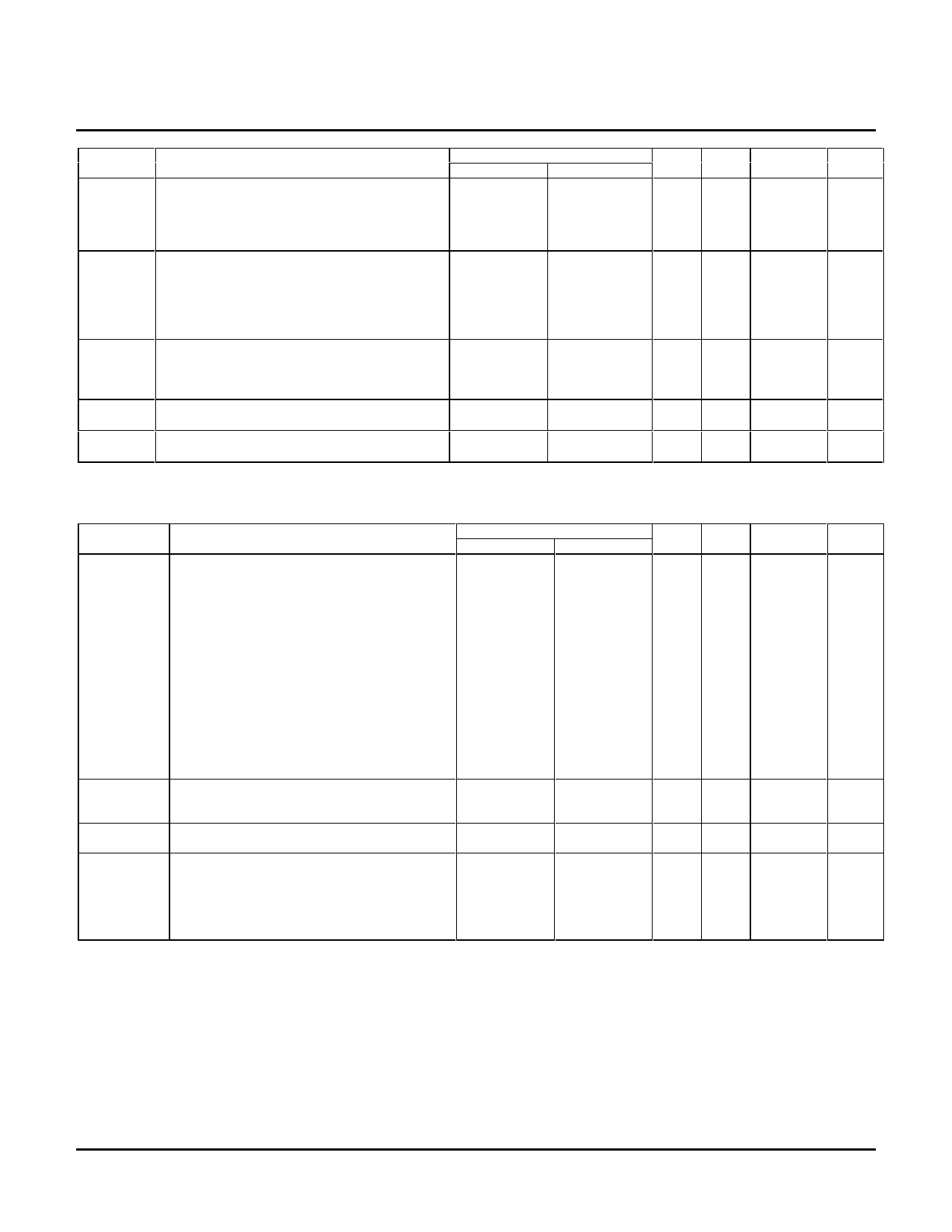
Pin Name
PAR
PCI_CLK
RST#
GNT#
REQ#
Description
Parity: This pin generates PCI parity and ensures
even parity across AD[31:0] and C/BE[3:0]#.
During the address phase, PAR is valid after one
clock. With data phases, PAR is stable one clock
after a write or read transaction.
PCI Clock: This input provides timing for all
transactions on the PCI bus to and from the
OZ6812. All PCI bus signals, except RST#, are
sampled and driven on the rising edge of
PCI_CLK. This input can be operated at
frequencies from 0 to 33 MHz.
Device Reset: This input is used to initialize all
registers and internal logic to their reset states
and place most OZ6812 pins in a HIGH-
impedance state.
Grant: This signal indicates that access to the bus
has been granted.
Request: This signal indicates to the arbiter that
the OZ6812 requests use of the bus.
Pin Number
LQFP
BGA
36
L3
21
G4
20
G2
2
B2
1
A1
Input Type
TTL I/O
Power
Rail
PCI_Vcc
Drive
PCI
Spec
-
I
PCI_Vcc
-
-
I
AUX_Vcc
-
TTL
I
- TO
PCI_Vcc
PCI_Vcc
PCI
Spec
PCI
Spec
Power Control and General Interface Pins
Pin Name
RI_OUT/
PME#
Description
Ring Indicate Out: This pin is Ring Indicate
when the following occurs while O2 Mode Control
B Register (index 2Eh) bit 7 is set to 1:
1) Power Control (Index+02h) bit 7 set to 1
2) Interrupt and General Control (Index+03h)
bit 7 set to 1
3) PCI O2Micro Control 2 (Offset: D4h) bit X =
0
Pin Number
LQFP
BGA
59
M8
Input Type
-
TO
Power
Rail
Aux_Vcc
Drive
4mA
Power Management Event: A power
management event is the process by which the
OZ6812 can request a change of its power
consumption state. Usually, a PME occurs
during a request to change from a power saving
state to the fully operational state.
SPKR_OUT# Speaker Output: This output can be used to
62
K8
TTL I/O Aux_Vcc 12mA
support PC Card audio output. See O2 Mode E
Register (Index + 3Eh), bit 1.
MF[6:0]
Multifunction Terminal [6:0]: See PCI 69-67, 65-64, L10, K9, N11, TTL I/O Aux_Vcc 12mA
Multifunction MUX Register (Offset:08h).
61-60
L9, N10-9, L8
SUSPEND# Suspend: This signal is used to protect the
70
internal registers from clearing when the PCI
N12
TTL
I
Aux_Vcc
-
RST# signal is asserted. When low, this signal is
used to mask the PCI RESET during suspend.
This pin can be used during suspend to prevent
controller reset.
OZ6812-SF-1.5
Page 5
Share Link: 