AIC1340 Ver la hoja de datos (PDF) - Analog Intergrations
Número de pieza
componentes Descripción
Lista de partido
AIC1340 Datasheet PDF : 7 Pages
| |||
AIC1340
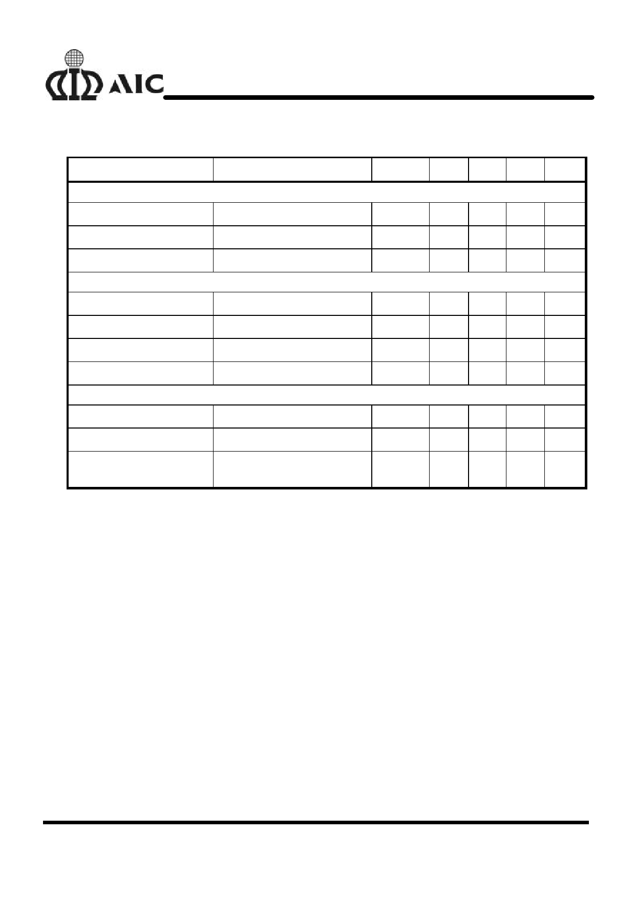
n ELECTRICAL CHARACTERISTICS (Continued)
PARAMETER
TEST CONDITIONS
SYMBOL MIN. TYP. MAX. UNIT
PWM CONTROLLER ERROR AMPLIFIER
DC GAIN
76
dB
Gain Bandwidth Product
GBWP
11
MHz
Slew Rate
COMP1=10pF
PWM CONTROLLER GATE DRIVER
SR
6
V/µS
Upper Drive Source
Upper Drive Sink
Lower Drive Source
Lower Drive Sink
PROTECTION
VCC=12V, VUGATE=11V
VCC=12V, VUGATE =1V
VCC=12V, VLGATE=11V
VCC=12V, VLGATE=1V
RUGH
RUGL
RLGH
RLGL
5.2 6.5
Ω
3.3 5
Ω
4.1 6
Ω
3
5
Ω
OCSET Current Source
Soft-Start Current
VOCSET=4.5V DC
IOCSET
ISS
170 200 230 µA
11
µA
Chip Shutdown Soft Start
Threshold
1.0
V
n PIN DESCRIPTIONS
Pin 1:
PHASE: Over-current detection pin. Con-
nect the PHASE pin to source of
the external high-side N-
MOSFET. This pin detects the
voltage drop across the high-side
N-MOSFET RDS(ON) for over-
current protection.
Pin 2:
UGATE: External high-side N-MOSFET
gate drive pin. Connect UGATE
to gate of the external high-side
N-MOSFET.
Pin 3: SD:
To shut down the system, active
high or floating.
Pin 4: VCC: The chip power supply pin. It also
Pin 5: SS:
Pin 6: FB2:
provides the gate bias charge for
all the MOSFETs controlled by
the IC. Recommended supply
voltage is 12V.
Soft-start pin. Connect a capaci-
tor from this pin to ground. This
capacitor, along with an internal
10µA (typically) current source,
sets the soft-start interval of the
converter.
Pulling this pin low will shut down
the IC.
Connect this pin to a resistor di-
vider to set the linear regulator
output voltage.
5
Share Link: 