DCR1006SF Ver la hoja de datos (PDF) - Dynex Semiconductor
Número de pieza
componentes Descripción
Lista de partido
DCR1006SF Datasheet PDF : 8 Pages
| |||
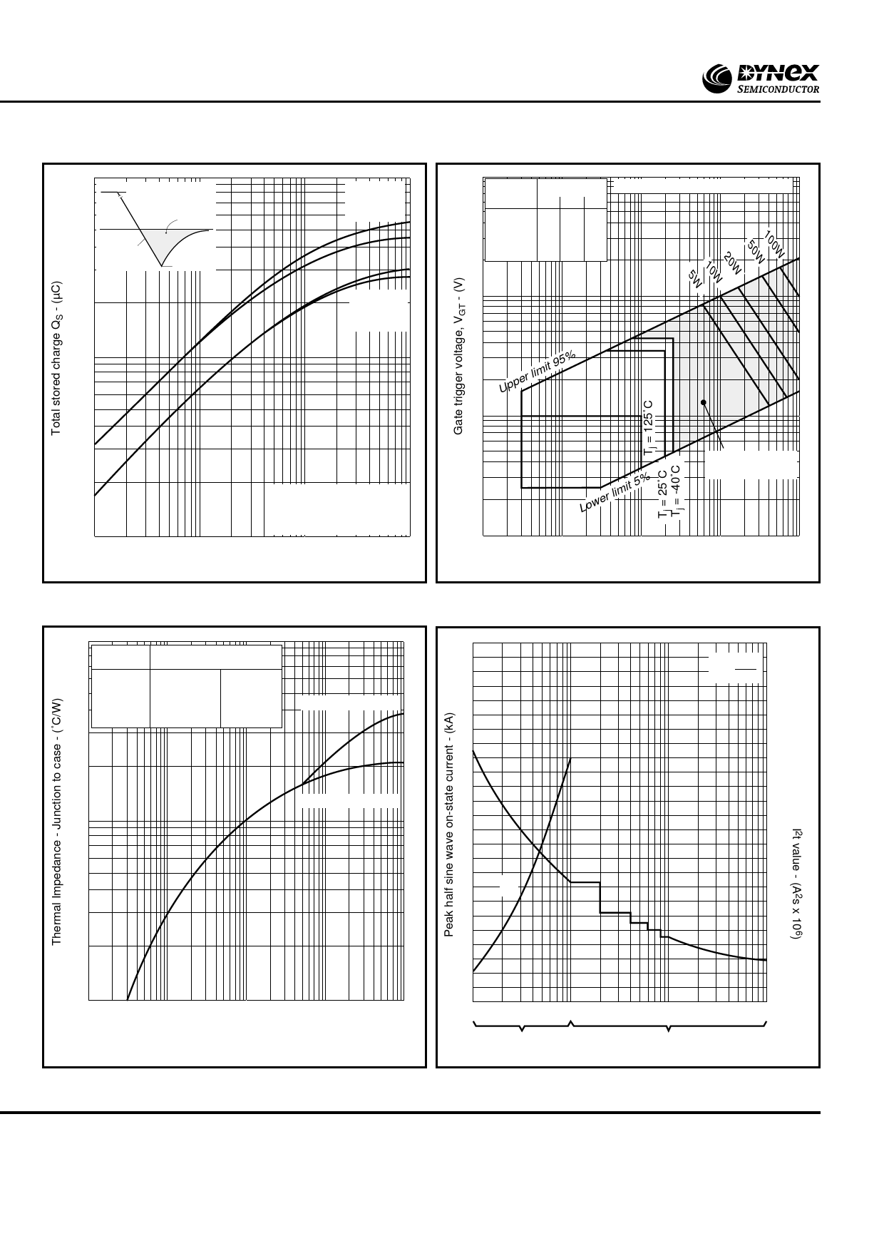
DCR1006SF
10000
IT
QS
dI/dt
IRR
1000
IT = 2000A
IT = 1000A
Max. value
IT = 2000A
IT = 1000A
Min. value
100
0.1
Conditions;
QS is total integral charge
Tl = 125˚C
1.0
10
100
Rate of decay of on-state current dI/dt - (A/µs)
Fig.4 Stored charge
100
Pulse width Frequency Hz
µs
50 100 400
100 150 150 150
200 150 150 125
500 150 150 100
1ms 150 50 25
10ms 20 - -
Table gives pulse power PGM in Watts
10
Upper limit 95%
1
VGD
0.1
0.001
Lower limit 5%
Region of certain
triggering
0.01
0.1
1
10
Gate trigger current, IGT - (A)
Fig.5 Gate characteristics
0.1
50
Conduction
Effective thermal resistance
Junction to case ˚C/W
Double side Anode side
d.c.
0.022
0.038
Halfwave
0.024
0.040
Anode side cooled
3 phase 120˚
0.026
0.042
40
6 phase 60˚
0.027
0.043
I2t = Î2 x t
2
1.5
30
1.25
Double side cooled
0.01
20
1.0
I2t
10
0.75
0.001
0.001
0.01
0.1
1.0
10
Time - (s)
Fig.6 Transient thermal impedance - junction to case
0
0.5
1
10 1 2 3 45 10 20 30 50
ms
Cycles at 50Hz
Duration
Fig.7 Surge (non-repetitive) on-state current vs time (with
50% VRRM at Tcase = 125˚C)
6/8
www.dynexsemi.com
Share Link: 