MAX1735(2000) Ver la hoja de datos (PDF) - Maxim Integrated
Número de pieza
componentes Descripción
Lista de partido
MAX1735 Datasheet PDF : 10 Pages
| |||
200mA, Negative-Output, Low-Dropout
Linear Regulator in SOT23
-6.5V TO -2.5V
INPUT
CIN
1µF CERAMIC
ON
GND OFF
ON
-5.0V,-3.0V, OR -2.5V
FIXED
OUTPUT
IN
OUT
COUT
1µF CERAMIC
MAX1735
SHDN
SET
GND
-6.5V TO -2.5V
INPUT
CIN
1µF CERAMIC
ON
GND OFF
ON
IN
OUT
MAX1735
SHDN
SET
GND
-5.5V TO -1.25V
ADJUSTABLE
OUTPUT
COUT
R1
1µF
CERAMIC
R2
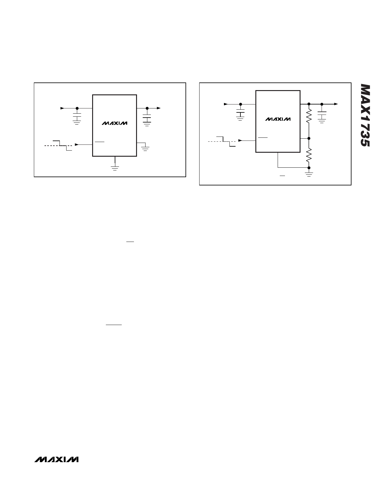
Figure 2. Typical Application Circuit with Preset Output Voltage
In adjustable mode, an output voltage between -5.5V and
-1.25V is selected using two external resistors connected
as a voltage-divider from OUT to SET (Figure 3). The out-
put voltage is determined by the following equation:
VOUT
=
VSET
1+
R1
R2
where VSET = VREFERENCE = -1.25V when in regulation.
Since the input bias current at SET is <100nA, use
large resistance values for R1 and R2 to minimize
power consumption in the feedback network. A typical
value of 100kΩ for R2 is acceptable for most applica-
tions. Higher values consume less current at the
expense of output voltage accuracy. The above equa-
tion solved for R1 is:
R1= R2
VOUT
VSET
− 1
For preset output voltage mode, connect SET directly
to GND.
Shutdown
In shutdown, the N-channel MOSFET, control circuitry,
reference, and all internal circuits are turned off, reduc-
ing supply current to typically 1nA. SHDN can be dri-
ven by either a positive or negative voltage. Drive
SHDN above +1.6V or below -1.6V to turn the regulator
on. To turn the regulator off, drive SHDN to GND. For
always-on operation, connect SHDN to IN. By including
a positive threshold at SHDN, it can be driven by a
standard 5V TTL level without needing level-shifting cir-
cuitry.
( ) VOUT = VSET 1 + R1
R2
Figure 3. Typical Application Circuit with Adjustable Output
Voltage
Current Limiting
The MAX1735 features a current limit that protects the
regulator. Short-circuit output current is typically
515mA. The output will withstand a short to ground
indefinitely; however, if the increased power dissipation
heats the die to +160°C, the thermal overload protec-
tion will shut off the regulator, preventing damage to the
IC.
Thermal Overload Protection
The thermal overload protection circuit protects the reg-
ulator against overheating due to prolonged overload
conditions. When the die temperature exceeds +160°C,
an on-chip thermal sensor disables the pass transistor,
allowing the IC to cool. The thermal sensor reenables
the pass MOSFET once the die temperature drops
15°C. A continuous short-circuit fault condition results in
a cyclical enabling and disabling of the output.
Thermal overload protection is designed to safeguard
the MAX1735 in the event of overload fault conditions.
For normal operation, do not exceed the absolute maxi-
mum junction temperature rating of +150°C. Junction
temperature is greater than ambient by an amount
depending on package heat dissipation and the ther-
mal resistance from the junction to ambient (θJA):
TJUNCTION = TAMBIENT + (θJA)(PDISSIPATION)
where
θJA for the 5-pin SOT23 is about 0.140°C/mW.
_______________________________________________________________________________________ 7
Share Link: 