MAX2035 Ver la hoja de datos (PDF) - Maxim Integrated
Número de pieza
componentes Descripción
Lista de partido
MAX2035 Datasheet PDF : 13 Pages
| |||
Ultrasound Variable-Gain Amplifier
AC ELECTRICAL CHARACTERISTICS (continued)
(Figure 2, VCC = VREF = 4.75V to 5.25V, VCM = (3/5)VREF, VGND = 0, PD = 0, no RF signals applied, capacitance to GND at each of
the VGA differential outputs is 60pF, differential capacitance across the VGA outputs is 10pF, RL = 1kΩ, TA = 0°C to +70°C. Typical
values are at VCC = VREF = 5V, TA = +25°C, unless otherwise noted.) (Note 2)
PARAMETER
SYMBOL
CONDITIONS
MIN TYP MAX UNITS
Channel-to-Channel Crosstalk
VOUT = 1VP-P differential, fRF = 10MHz,
VG_CTL set for +20dB of gain
-80
dB
Maximum Output Voltage at
Clamp ON
Maximum Output Voltage at
Clamp OFF
VG_CLAMP_MODE = 0,
VG_CTL set for +20dB of gain,
350mVP-P differential input
VG_CLAMP_MODE = 1,
VG_CTL set for +20dB of gain,
350mVP-P differential input
2.2
VP-P
differential
3.4
VP-P
differential
Note 2: Specifications at TA = +25°C and TA = +70°C are guaranteed by production test. Specifications at TA = 0°C are guaranteed
by design and characterization.
Note 3: Noise performance of the device is dependent on the noise contribution from the supply to VREF. Use a low-noise supply for
VREF. VCC and VREF can be connected together to share the same supply voltage if the supply for VCC exhibits low noise.
Note 4: See the Ultrasound-Specific IMD3 Specification section.
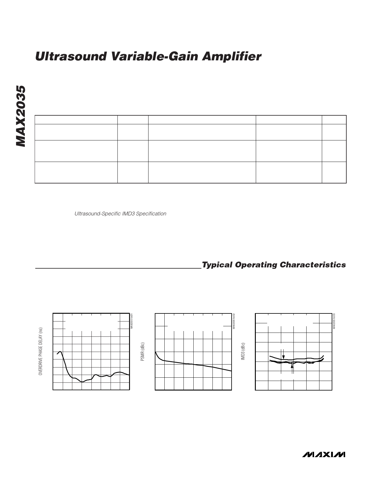
Typical Operating Characteristics
(Figure 2, VCC = VREF = 4.75V to 5.25V, VGND = 0, PD = 0, VG_CLAMP_MODE = 1, fRF = 5MHz, capacitance to GND at each of the
VGA differential outputs is 60pF, differential capacitance across the VGA outputs is 10pF, RL = 1kΩ, TA = 0°C to +70°C. Typical val-
ues are at VCC = VREF = 5V, VCM = 3.0V, TA = +25°C, unless otherwise noted.)
5.0
4.5
4.0
3.5
3.0
2.5
2.0
1.5
1.0
0.5
0
0
OVERDRIVE PHASE DELAY
vs. FREQUENCY
VIN1 = 35mVP-P DIFFERENTIAL
VIN2 = 87.5mVP-P DIFFERENTIAL
GAIN = 20dB
2.5 5.0 7.5 10.0 12.5 15.0 17.5 20.0
FREQUENCY (MHz)
POWER-SUPPLY MODULATION RATIO
-30
VOUT = 1.5VP-P DIFFERENTIAL
-40
VMOD = 50mVP-P, fCARRIER = 5MHz,
GAIN = 20dB
-50
-60
-70
-80
-90
0
25 50 75 100 125 150 175 200
FREQUENCY (kHz)
TWO-TONE ULTRASOUND-SPECIFIC
IMD3 vs. GAIN
0
VOUT = 1VP-P DIFFERENTIAL
-10
GAIN = 20dB
-20
-30
f = 10MHz
-40
-50
-60
f = 2MHz, 5MHz
-70
-80
-15 -5
5 15 25 35 45
GAIN (dB)
4 _______________________________________________________________________________________
Share Link: 