MAX8559 Ver la hoja de datos (PDF) - Maxim Integrated
Número de pieza
componentes Descripción
Lista de partido
MAX8559
Maxim Integrated

MAX8559 Datasheet PDF : 12 Pages
| |||
Dual, 300mA, Low-Noise Linear Regulator
with Independent Shutdown in UCSP or TDFN
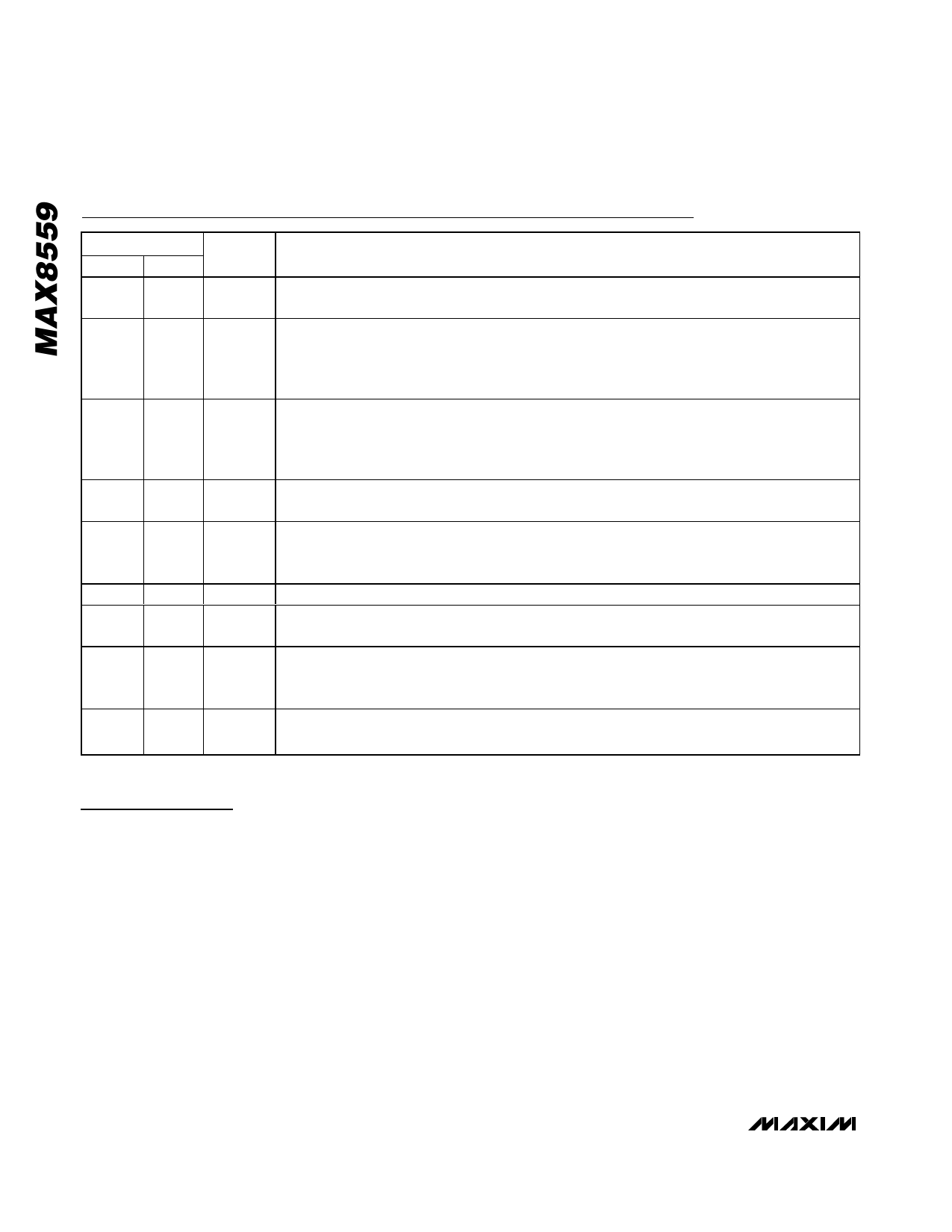
Pin Description
PIN
TDFN UCSP
1
A1
2
A2
3
A3
4
A4
5
B4
6
B3
7
B2
8
B1
EP
—
NAME
FUNCTION
INA
LDO A Regulator Input. Connect to INB. Input voltage can range from 2.5V to 6.5V. Bypass INA
with a ceramic capacitor to GND (see the Capacitor Selection and Regulator Stability section).
SHDNA
Shutdown A Input. A logic-low on SHDNA shuts down regulator A. If SHDNA and SHDNB are both
low, both regulators and the internal reference are off and the supply current is reduced to 10nA
(typ). If either SHDNA or SHDNB is a logic high, the internal reference is on. Connect SHDNA to
INA for always-on operation of regulator A.
SHDNB
Shutdown B Input. A logic-low on SHDNB shuts down regulator B. If SHDNA and SHDNB are both
low, both regulators and the internal reference are off and the supply current is reduced to 10nA
(typ). If either SHDNA or SHDNB is a logic high, the internal reference is on. Connect SHDNB to
INB for always-on operation of regulator B.
INB
LDO B Regulator Input. Connect to INA. Input voltage can range from 2.5V to 6.5V. Bypass INB
with a ceramic capacitor to GND (see the Capacitor Selection and Regulator Stability section).
OUTB
GND
BP
Regulator B Output. OUTB can source up to 300mA continuous current. Bypass OUTB with a
ceramic capacitor to GND (see the Capacitor Selection and Regulator Stability section). During
shutdown, OUTB is internally discharged to GND through a 385Ω resistor.
Ground
Reference Noise Bypass. Bypass BP with a low-leakage 0.01µF ceramic capacitor for reduced
noise at both outputs.
OUTA
Regulator A Output. OUTA can source up to 300mA continuous current. Bypass OUTA with a
ceramic capacitor to GND (see the Capacitor Selection and Regulator Stability section). During
shutdown, OUTB is internally discharged to GND through a 385Ω resistor.
Exposed Connect to ground plane. EP also functions as a heatsink. Solder to the circuit-board ground
Paddle plane to maximize thermal dissipation.
Detailed Description
The MAX8559 is a dual, low-noise, low-dropout, low-qui-
escent-current linear regulator designed primarily for
battery-powered applications. The regulators are avail-
able with preset 1.5V to 3.3V output voltages. These out-
puts can supply loads up to 300mA with a 4.7µF output
capacitor, or up to 150mA with a 2.2µF output capacitor.
As illustrated in the Functional Diagram, the MAX8559
consists of a 1.25V reference, error amplifiers, P-chan-
nel pass transistors, internal feedback voltage-dividers,
and autodischarge circuitry.
Feedback Control Loop
The 1.25V bandgap reference is connected to the error
amplifier’s inverting input. The error amplifier compares
this reference with the feedback voltage and amplifies
the difference. If the feedback voltage is lower than the
reference voltage, the pass-transistor gate is pulled
lower, allowing more current to pass to the output and
increasing the output voltage. If the feedback voltage is
too high, the pass-transistor gate is pulled up, allowing
less current to pass to the output. The output voltage is
fed back through an internal resistor voltage-divider
connected to OUT_.
Internal P-Channel Pass Transistor
The MAX8559 features two 0.6Ω P-channel MOSFET
pass transistors. A P-channel MOSFET provides sever-
al advantages over similar designs using PNP pass
transistors, including longer battery life. It requires no
base drive, reducing quiescent current considerably.
PNP-based regulators waste considerable current in
dropout when the pass transistor saturates, and they
also use high base-drive currents under large loads.
The MAX8559 does not suffer from these problems,
and with both outputs on it only consumes 180µA of
6 _______________________________________________________________________________________
Share Link: