MAX8645X Ver la hoja de datos (PDF) - Maxim Integrated
Número de pieza
componentes Descripción
Lista de partido
MAX8645X Datasheet PDF : 14 Pages
| |||
1x/1.5x/2x White LED Charge Pumps with Two
LDOs in 4mm x 4mm TQFN
INITIAL tHI
0
≥ 200μs
1
23
45
ENM1 AND ENM2
OR
ENF
tSOFT-START
32/32
IM_ OR IF_
SHUTDOWN
31/32
30/32
tLO
500ns TO 250μs
29/32 28/32 27/32
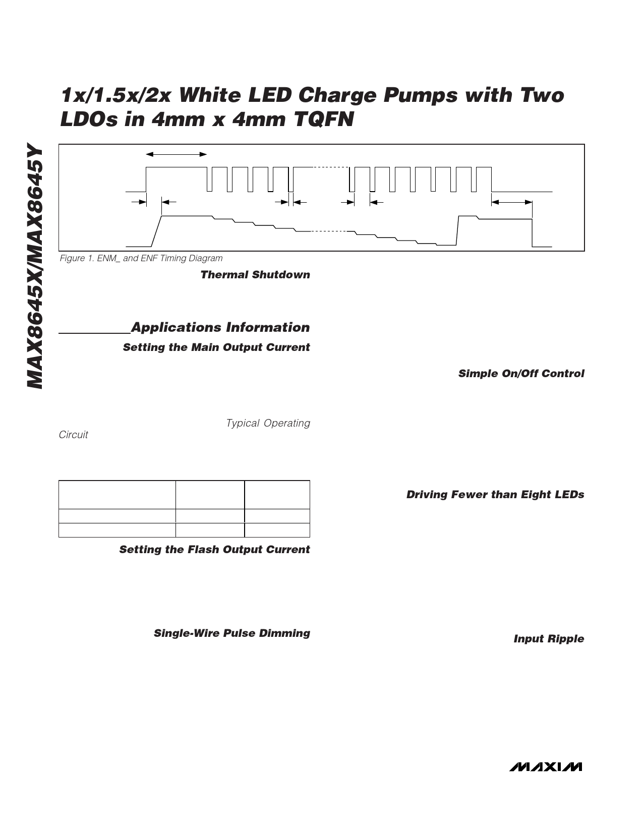
Figure 1. ENM_ and ENF Timing Diagram
Thermal Shutdown
The MAX8645X/MAX8645Y include a thermal-limit circuit
that shuts down the IC at approximately +160°C. Turn-
on occurs after the IC cools by approximately 20°C.
Applications Information
Setting the Main Output Current
SETM controls M1–M6 regulation current. Current flow-
ing into M1, M2, M3, M4, M5, and M6 is a multiple of
the current flowing out of SETM:
IM1 = IM2 = IM3 = IM4 = IM5 = IM6 = K x (0.6V / RSETM)
where K = 230, and RSETM is the resistor connected
between SETM and GND (see the Typical Operating
Circuit).
Table 1. ENM1/ENM2 States
ENM1/ENM2 STATES
BRIGHTNESS
M1–M6
CURRENT
ENM1 = low, ENM2 = low
Shutdown
ENM1 = high, ENM2 = high Full brightness
0
230 x ISETM
Setting the Flash Output Current
SETF controls the F1, F2 regulation current. Current
flowing into F1 and F2 is a multiple of the current flow-
ing out of SETF:
IF1 = IF2 = N x (0.6V / RSETF)
where N = 1380.
Single-Wire Pulse Dimming
For more dimming flexibility or to reduce the number of
control traces, the MAX8645X/MAX8645Y support serial
pulse dimming. Connect ENM1 and ENM2 together to
enable single-wire pulse dimming of the main LEDs (or
ENF only for single-wire pulse dimming of the flash
LEDs). See Figure 2. When ENM1 and ENM2 (or ENF)
go high simultaneously, the main (or flash) LEDs are
enabled at full brightness. Each subsequent low-going
pulse (500ns to 250µs pulse width) reduces the LED
27 28 29 30 31 32
tHI
≥ 500ns
tSHDN
32/32 31/32 2.5ms (typ)
5/32 4/32 3/32 2/32 1/32
SHUTDOWN
current by 3.125% (1/32), so after one pulse, the LED
current is 96.9% (or 31/32) x ILED. The 31st pulse
reduces the current to 0.03125 x ILED. The 32nd pulse
sets the LED current back to ILED. Figure 1 shows a
timing diagram for single-wire pulse dimming. Because
soft-start is longer than the initial tHI, apply dimming
pulses quickly upon startup (after initial tHI) to avoid
LED current transitioning through full brightness.
Simple On/Off Control
If dimming control is not required, connect ENM1 to
ENM2 for simple on/off control. Drive both ENM1 and
ENM2 to a logic-level high to turn on the main LEDs.
Drive both ENM1 and ENM2 to a logic-level low to turn
off the main LEDs. ENF is the simple on/off control for
the flash LEDs. Drive ENF to a logic-level high to turn
on the flash LEDs. Drive ENF to a logic-level low to turn
off the flash LEDs. In this case, LED current is set by
the values of RSETM and RSETF.
Driving Fewer than Eight LEDs
When driving fewer than eight LEDs, two connection
schemes can be used. The first scheme is shown in
Figure 3 where LED drivers are connected together.
This method allows increased current through the LED
and effectively allows total LED current to be ILED multi-
plied by the number of connected drivers. The second
method of connection is shown in Figure 4 where stan-
dard white LEDs are used and fewer than eight are
connected. This scheme does not alter current through
each LED but ensures that the unused LED driver is
properly disabled.
Input Ripple
For LED drivers, input ripple is more important than out-
put ripple. Input ripple is highly dependent on the
source supply’s impedance. Adding a lowpass filter to
the input further reduces input ripple. Alternately,
increasing CIN to 22µF cuts input ripple in half with only
a small increase in footprint. The 1x mode always has
very low input ripple.
10 ______________________________________________________________________________________
Share Link: 