MM1311BD Ver la hoja de datos (PDF) - Mitsumi
Número de pieza
componentes Descripción
Lista de partido
MM1311BD Datasheet PDF : 11 Pages
| |||
MITSUMI
I2C BUS
SDA
I2C BUS Control 4-Input 1-Output AV Switch MM1311
SCL
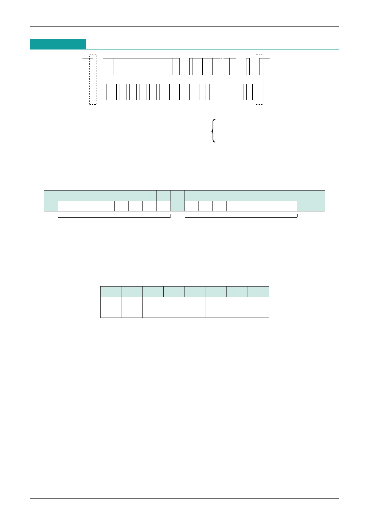
S 1 2 3 4 5 6 7 8 A 1 2 3 ·· 8 A P
S:Start Condition
P:Stop Condition
ACK:Acknowledge
The I2C BUS is a BUS system developed by Philips for internal use in equipment. Data transmission is carried
out by the two SDA and SCL lines, in byte units, with the MSB first from start condition.
Control Register
The control register contains data sent from the master in order to determine the status of each switch.
Slave address
R/W
Control register
S
A
AP
1 0 0 1 0 0 0/1 0
b7 b6 b5 b4 b3 b2 b1 b0
Address byte
Control data
The data format is set as shown in the figure above. The first 7 bits in the address byte are allocated to the
slave address, and the remaining 1 bit is allocated to the read/write bit. The read/write bit is set at 0 when
using as a control register.
The MM1311 slave address can be selected as 90H/92H depending on the status of the ADR pin. When the
ADR pin is low it is 90H. The relationship between the control register bits and switch control is as shown
below.
b7 b6
Audio S/Comp
Gain Select
b5 b4 b3
Video-Select
b2 b1 b0
Audio-Select
The control register bits are reset to 0 when power is applied.
MM1311 control is carried out by the 2-byte structure of the 1 address byte and 1 control data byte. All of the
remaining data (third byte and after) are ignored.
Refer to the separate tables for details on switch control.
Share Link: 