MSM51V18160A Ver la hoja de datos (PDF) - Oki Electric Industry
Número de pieza
componentes Descripción
Lista de partido
MSM51V18160A Datasheet PDF : 4 Pages
| |||
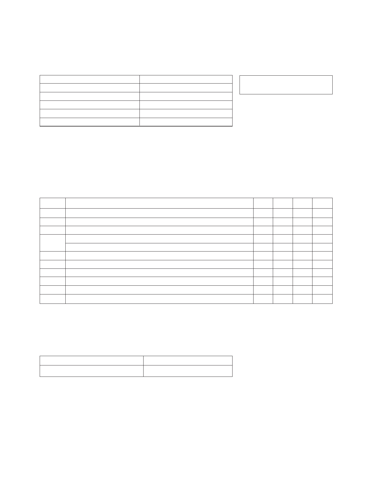
MSA-0700 Absolute Maximum Ratings
Parameter
Absolute Maximum[1]
Device Current
60 mA
Power Dissipation[2,3]
275 mW
RF Input Power
Junction Temperature
Storage Temperature
+13 dBm
200°C
–65 to 200°C
Notes:
1. Permanent damage may occur if any of these limits are exceeded.
2. TMounting␣ Surface = 25°C.
3. Derate at 20 mW/°C for TMounting␣ Surface ␣ > 186 °C.
4. The small spot size of this technique results in a higher, though more
accurate determination of θjc than do alternate methods. See MEASURE-
MENTS section “Thermal Resistance” for more information.
Thermal Resistance[2,4]:
θjc = 50°C/W
Electrical Specifications[1], TA = 25°C
Symbol
Parameters and Test Conditions[2]: Id = 22 mA, ZO = 50 Ω
GP
Power Gain (|S21| 2)
∆GP
Gain Flatness
f = 0.1 GHz
f = 0.1 to 1.5 GHz
f3 dB
3 dB Bandwidth
VSWR
Input VSWR
Output VSWR
f = 0.1 to 2.5 GHz
f = 0.1 to 2.5 GHz
NF
50 Ω Noise Figure
f = 1.0 GHz
P1 dB Output Power at 1 dB Gain Compression
f = 1.0 GHz
IP3
Third Order Intercept Point
f = 1.0 GHz
tD
Group Delay
f = 1.0 GHz
Vd
Device Voltage
dV/dT Device Voltage Temperature Coefficient
Units Min.
dB
dB
GHz
dB
dBm
dBm
psec
V
3.6
mV/°C
Typ. Max.
13.5
± 0.6
2.5
2.0:1
1.6:1
4.5
5.5
19.0
130
4.0 4.4
–7.0
Notes:
1. The recommended operating current range for this device is 15 to 40 mA. Typical performance as a function of current
is on the following page.
2. RF performance of the chip is determined by packaging and testing 10 devices per wafer in a dual ground configuration.
Part Number Ordering Information
Part Number
Devices Per Tray
MSA-0700-GP4
up to 100
6-387
Share Link: 