MSM6946GS-K Ver la hoja de datos (PDF) - Oki Electric Industry
Número de pieza
componentes Descripción
Lista de partido
MSM6946GS-K Datasheet PDF : 25 Pages
| |||
¡ Semiconductor
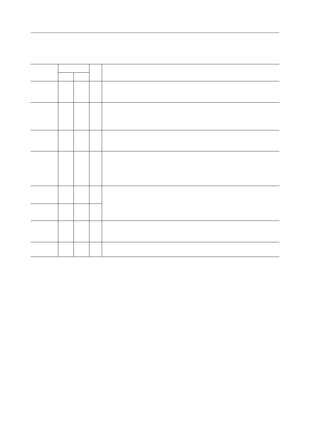
MSM6926/6946
Input/Output
Name
CS
RS1
XD
RD
SG2
SG1
AIN
AO
Pin No.
I/O
RS GS-K
6 3O
74I
99I
10 10 O
18 22 O
20 24 O
21 26 I
25 34 O
Description
Clear to send signal output. The digital "High" level indicates the "OFF" state and
digital "Low" indicates the "ON" state. This output goes "Low" at the end of a delay
(RS/CS delay) initiated when RS1 (Request to send) goes "Low".
Request to send signal input. The digital "High" level indicates the "OFF" state.
The digital "Low" level indicates the "ON" state and instructs the modem to enter
the transmit mode. This input must remain "Low" for the duration of data
transmission. "High" turns the transmitter off.
This is digital data to be modulated and transmitted via AO. Digital "High" will be
transmitted as "Mark". Digital "Low" will be transmitted as "Space". No signal
appears at AO unless RS1 is "Low".
Digital data demodulated from AIN is serially available at this output. Digital
"High" indicates "Mark" and digital "Low" indicates "Space". For example, under
the following condition, this output is forced to be "Mark" state because the data
may be invalid.
• When CD2 (Carrier detect) is in the "OFF" state.
The SG1 and ST2 are built-in analog signal grounds. SG2 is used only for
Carrier detect function. The DC voltage of SG1 is approximately 6 V, so the
analog line interface must be implemented by AC coupling. See Fig. 9. To make
impedance lower and ensure the device performance, it is necessary to put
bypass capacitors on SG1 and SG2 in close physical proximity to the device.
This is the input for the analog signal from the phone line. The modem extracts
the information in this modulated carrier and converts it into a serial data stream
for presentation at RD output.
This analog output is the modulated carrier to be conditioned and sent over the
phone line.
6/25
Share Link: 