PBL38571 Ver la hoja de datos (PDF) - Ericsson
Número de pieza
componentes Descripción
Lista de partido
PBL38571 Datasheet PDF : 14 Pages
| |||
PBL 385 71
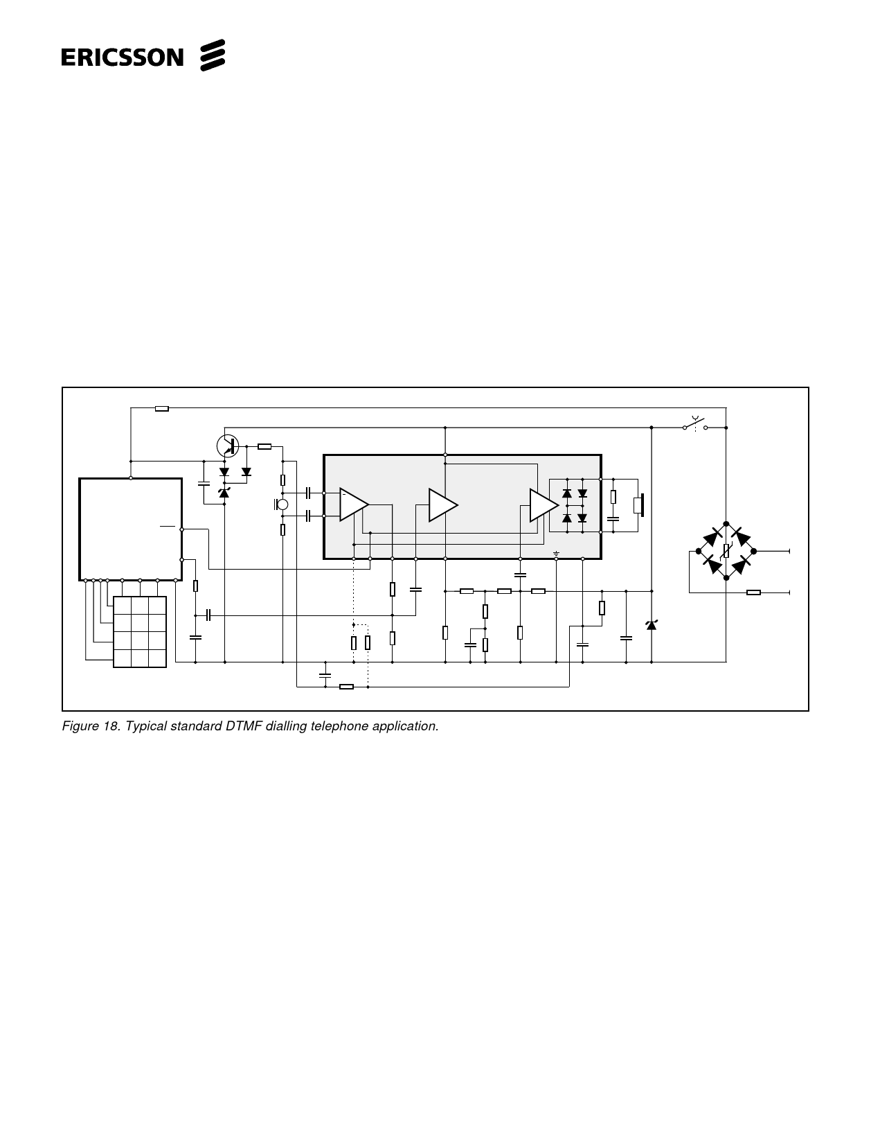
Power supply V+C. (See fig.18)
PBL 385 71 generates its own DC
supply V+C dependent of line current with
an internal shunt regulator. This regulator
senses the line voltage VL via R3 and line
current via R6 in order to set the correct
V+C so the circuit can generate the required
DC characteristic for a given line resistance
RLine and the line feeding data of the
exchange. A decoupling capacitor is
needed between pins +C and -L. The V+C
supply changes its voltage linearly with the
line current. It can be used to feed an
electret microphone. Caution must be ta-
ken though not to drain too much current
out of this output because it will affect the
internal quick start circuit by locking itself
into active state. (max. permissible current
drain 700µA)
Care has to be taken when deci-
ding the resistance value of R3. See fig.6.
All resistances that are applied from +Line
to ground (-Line) will be in parallel, forming
the real impedance towards the line. This
will sometimes result in, that the ohmic
value of R3 is increased in order to comply
to the impedance specification towards
the line. The speech circuit sinks ≈ 1mA
into pin 6, which means that the working
voltage for the speech function V+ will
decrease with increasing R3, thus starving
in the end the circuit of its working voltage
. This dependency is often falsely taken as
a sign of that the circuit does not work
down to the low line current specified, but
in fact it is the working voltage at pin 6 that
has become too low. It is obvious that this
problem is also connected into what kind
of DC-characteristic is set. See fig. 8.
1-5M
VDD
CMOS
DIALLER
+
47µF
MUTE
DTMF
GND
12 3
456
789
*0 #
15k
5.1V
200Ω
MIC.
200 Ω
1
1µF
10
AM
11 +
1µF
87
9
PBL 385 71
AT
AR
3
2
4,5,
12,13
14
R2
+
100 µF
1k
18k
22k
R1
100nF
910Ω
75 Ω
100nF
6.2k
560Ω
11k
47nF
62k
11k
15
16
+6
100 Ω
1nF
R3
910 Ω
+ C1
47µ F
15V
C2
1W
15nF
Hook
switch
1N4007
1N4007
1N4007
1N4007
Teleph
line
10Ω
Figure 18. Typical standard DTMF dialling telephone application.
11
Share Link: 