CS5513-BS Ver la hoja de datos (PDF) - Cirrus Logic
Número de pieza
componentes Descripción
Lista de partido
CS5513-BS Datasheet PDF : 24 Pages
| |||
CS5510/11/12/13
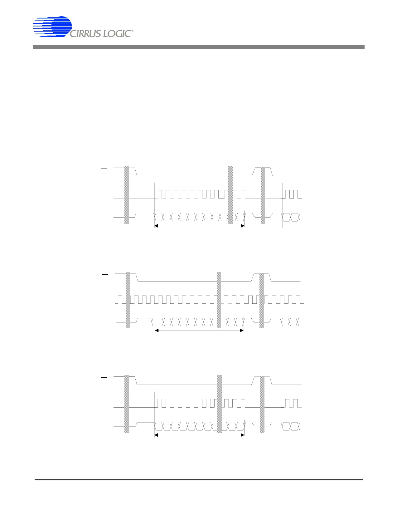
2.5.3 Output Coding
As shown in Tables 1 and 2, the CS5510/11/12/13
present output conversions as 24-bit conversion
words. The first bit of the conversion word indi-
cates that a conversion is done through SDO fall-
ing from a logic high to a logic low level. The first
and the fourth bits output will always be zero. The
second and third bits are error flags, representing
an overflow or oscillation condition. In the
CS5510/11, there are four more bits of zero, and
the remaining 16 bits are the conversion data, out-
put MSB first (Table 2). In the CS5512/13, the final
CS
20 bits are the conversion data, which is output
MSB first (Table 1).
Bits D22-D21 are the two flag bits. The OF (Over-
range Flag) bit is set to a logic 1 any time the input
signal is more positive than positive full scale, or
more negative than negative full scale. It is cleared
back to logic 0 whenever a conversion word occurs
which is not overranged. The OD (Oscillation De-
tect) bit is set to a logic 1 any time that an oscillatory
condition is detected in the modulator. This does
not occur under normal operating conditions, but
may occur whenever the input to the converter is ex-
SCLK
SDO
0 OF OD 0 0 0 0 0 MSB
LSB
Data Tim e
24 SCLKs
00
Figure 17. Data Word Timing for the CS5511.
CS
SCLK
SDO
0 OF OD 0 MSB
LSB
Data Tim e
24 SCLKs
00
Figure 18. Data Word Timing for the CS5512.
CS
SCLK
SDO
0 OF OD 0 MSB
LSB
Data Tim e
24 SCLKs
00
Figure 19. Data Word Timing for the CS5513.
DS337F3
17
Share Link: 