XE2422H Ver la hoja de datos (PDF) - Unspecified
Número de pieza
componentes Descripción
Lista de partido
XE2422H Datasheet PDF : 20 Pages
| |||
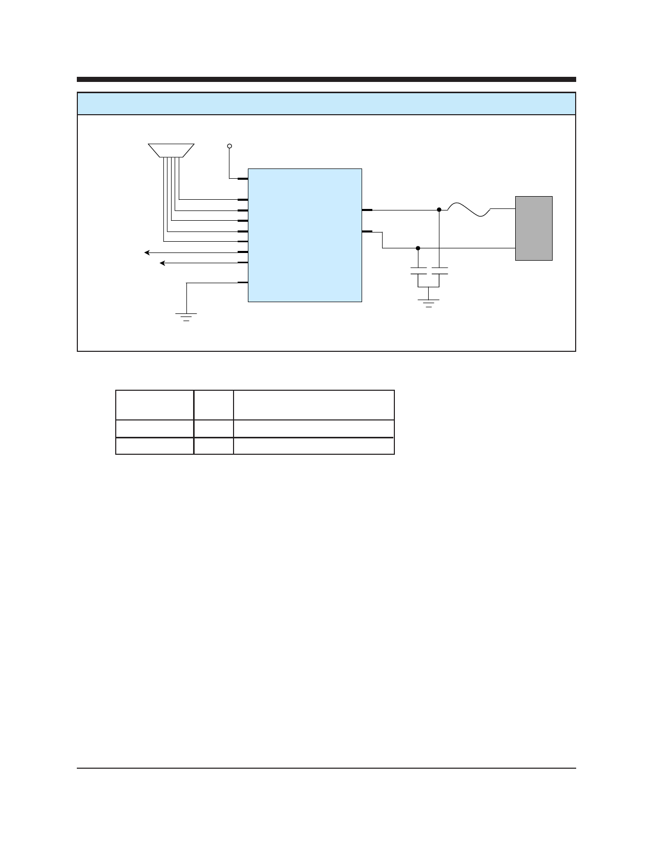
XE2422H Typical Connection Diagram
To Host Serial Port VCC
To System Reset
To System Interrupt
XE2422H
VCC
/DCD
/CTS
RXD
TXD
/RI
/Reset
/INT
GND
RING
TIP (22)
C1
RJ11
F1
C2
Parts List for XE2422H Typical Connection Diagram
Reference
Designation Qty
C1, C2
2
F1
1
Description
Cap. 1000 pfd, 1500V minimum
PTC, TR600-150
Notes:
1 Capacitors, C1 and C2, may be required for EMI filtering in your system. Without these components
you may experience unintended radiation when the telephone cable is attached. C1 and C2 are high-
voltage capacitors. We recommend the Johanson Dielectrics 502S47N102KV6T. This 1000 pfd, 3000
volt capacitor will direct the high frequency harmonics to the system ground. These capacitors must
be rated at a minimum of 1500 volts to maintain the isolation required by FCC Part 68 Rules.
3. F1 is a positive thermal coefficient (PTC) device which protects the modem from excessive current
flow. These devices are required for your system to pass UL60950. Fuses may be used in place of
the PTC’s
XECOM
(7)
XE2422H
Share Link: 