IA63484 Ver la hoja de datos (PDF) - InnovASIC, Inc
Número de pieza
componentes Descripción
Lista de partido
IA63484 Datasheet PDF : 32 Pages
| |||
IA63484
Advanced CRT Controller
Data Sheet
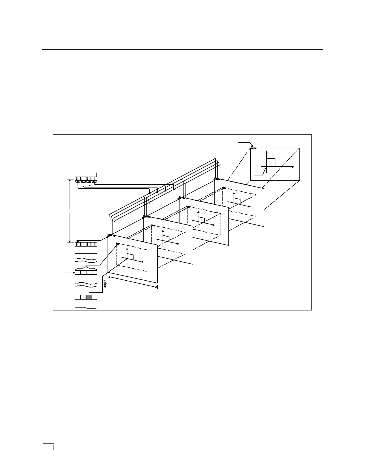
Address Space:
The ACRTC allows the host to issue commands in logical X-Y coordinates. The ACRTC then
converts the physical linear word addresses with bit field offsets in the frame buffer. Figure 7 shows
the relationship between the logical X-Y screen address and the frame buffer memory. The frame
buffer memory is organized as sequential 16 bit words. The host may specify 1, 2, 4, 8, or 16 physical
bits in the frame buffer. The system in the figure uses 4 bit logical pixels, allowing for 16 colors or
tones.
Figure 7: Logical/Physical Addressing
Physical Addressing
(Frame Buffer)
bit
bit
0
15
1 pixel data
MW
Logical Addressing
SAD
Display Screen
Y
(x,y)
X
Origin
SAD
Y
(x,y)
X
MW
Up to 4 logical screens may be mapped onto the ACRTC physical address space. The four screens
are the upper, base, lower, and window screens. The host first specifies the following:
• A logical screen starting address.
• A logical screen physical memory width (memory words per raster).
• A logical pixel physical memory width (bit per pixel).
• A logical origin physical address.
Then the ACRTC converts the logical pixel X-Y addresses issued by the host MPU or the drawing
processor to physical frame buffer addresses. The device also performs bit extraction and masking
to map logical pixel operations to 16 bit word frame buffer addresses.
Copyright © 2001
innovASIC
The End of Obsolescence™
ENG 21101041200
Page 12 of 32
www.innovasic.com
Customer Support:
1−888−824−4184
Share Link: 