PS9814 Ver la hoja de datos (PDF) - California Eastern Laboratories.
Número de pieza
componentes Descripción
Lista de partido
PS9814
California Eastern Laboratories.

PS9814 Datasheet PDF : 12 Pages
| |||
PS9814-1,-2
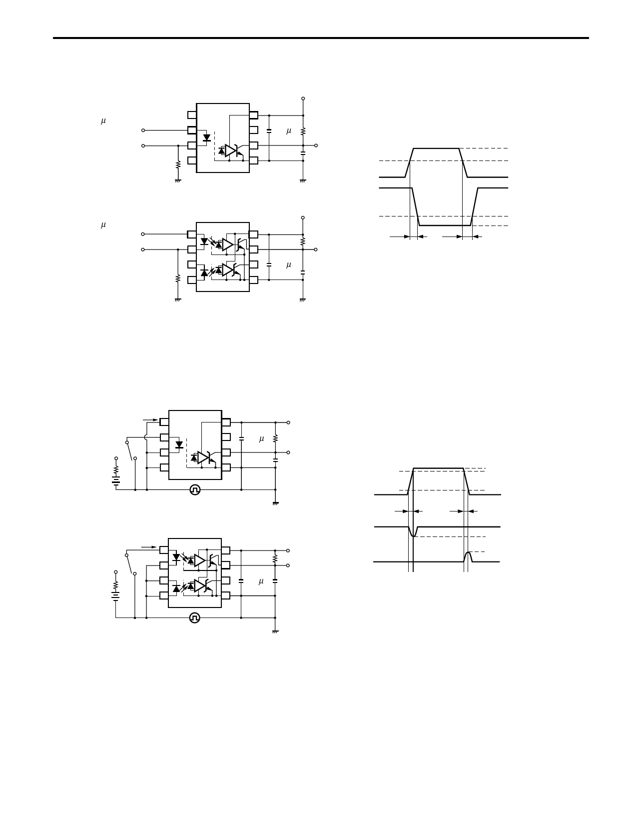
*3 Test circuit for propagation delay time
(PW = 1µs, Pulse input (IF)
Duty cycle = 1/10)
Input
(Monitor)
47 Ω
PS9814-1
VCC = 5 V
0.1 µF
RL = 350 Ω
VO (Monitor)
CL = 15 pF
Input
Output
PS9814-2
VCC = 5 V
(PW = 1µs, Pulse input (IF)
Duty cycle = 1/10)
RL = 350 Ω
tPHL
tPLH
Input
VO (Monitor)
(Monitor)
SHIELD
0.1 µF
47 Ω
SHIELD
CL = 15 pF
Remark CL includes probe and stray wiring capacitance.
(IF = 7.5 mA)
50%
1.5 V
VOL
*4 Test circuit for common mode transient immunity
SW IF
PS9814-1
0.1 µF
VCC = 5 V
RL = 350 Ω
VO (Monitor)
CL = 15 pF
SW IF
VCM
PS9814-2
SHIELD
SHIELD
0.1 µF
VCC = 5 V
RL = 350 Ω
VO (Monitor)
CL = 15 pF
VCM 90%
10%
tr
VO
(IF = 0 mA)
VO
(IF = 7.5 mA)
VCM
1 kV
0V
tf
VOH
2V
0.8 V
VOL
USAGE CAUTIONS
1. This product is weak for static electricity by designed with high-speed integrated circuit so protect against static electricity
when handling.
2. By-pass capacitor of 0.1 μF is used between VCC and GND near device. Also, ensure that the distance between the leads of
the photocoupler and capacitor is no more than 10 mm.
3. Avoid storage at a high temperature and high humidity.
6
Share Link: