SL6652DG20 Ver la hoja de datos (PDF) - Zarlink Semiconductor Inc
Número de pieza
componentes Descripción
Lista de partido
SL6652DG20 Datasheet PDF : 11 Pages
| |||
18
17
16
15
9
20
4k
7
10
13
19
14
12
200k
200k
SL6652
5
11
6
8
BAND-GAP
REFERENCE
2
3
4
1
40k
40k
BIAS
GENERAL DESCRIPTION
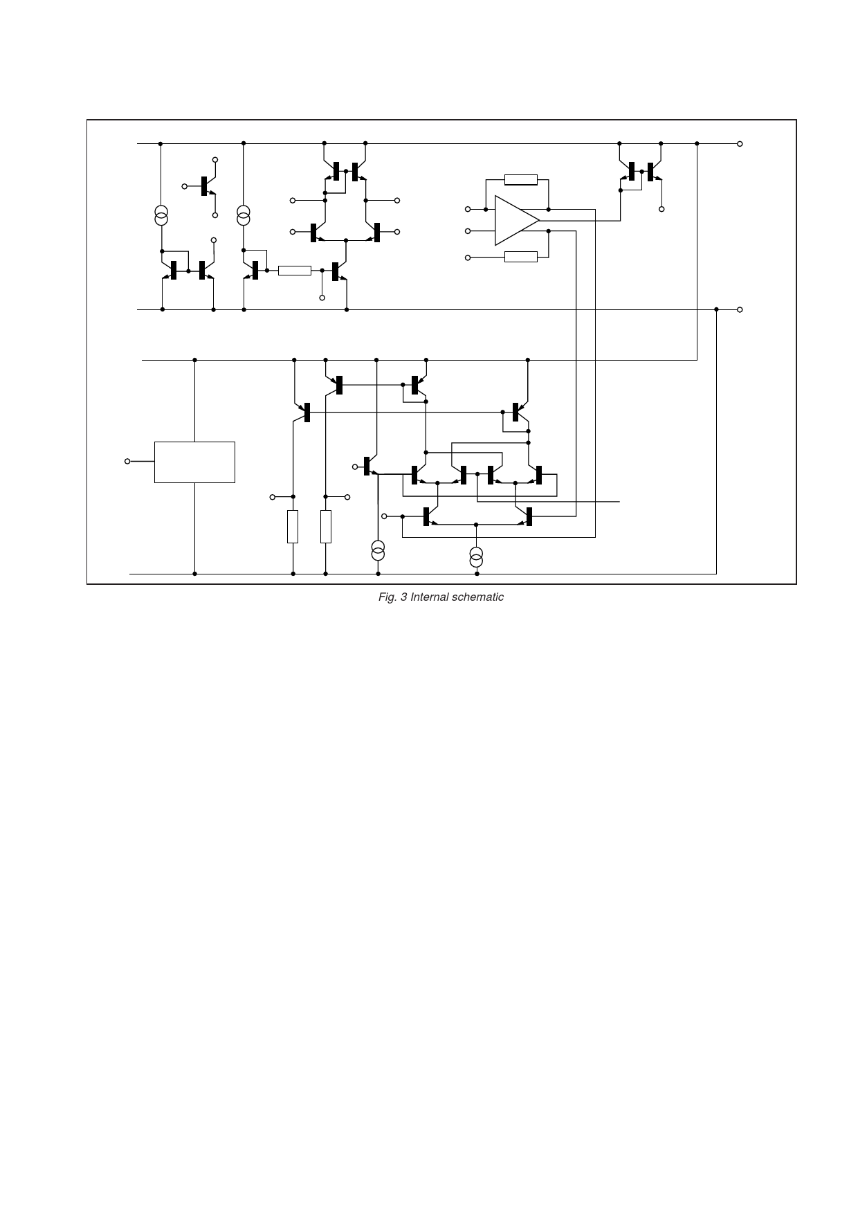
Fig. 3 Internal schematic
The SL6652 is a very low power, high performance
integrated circuit intended for IF amplification and
demodulation in FM radio receivers. It comprises:
of oscillator is suitable for the type of crystal and frequency
required; it may not always be adequate to duplicate the
design shown in this data sheet.
q A mixer stage for use up to lOOMHz
q An uncommitted transistor for use as an oscillator
q A current sink for biasing this transistor
q A limiting amplifier operating up to 1.5MHz
q A quadrature detector with differential AF output
q An RSSI (Received Signal Strength Indicator) output
IF amplifier
The limiting amplifier is capable of operation to at least 1
MHz and the input impedance is set by an external resistor to
match the ceramic filter. Because of the high gain, pins 12 and
13 must be adequately bypassed.
Mixer
The mixer is single balanced with an active load. Gain is
set externally by the load resistor although the value is
normally determined by that required for matching into the
ceramic filter. It is possible to use a tuned circuit but an
increase in mixer gain will result in a corresponding reduction
of the mixer input intercept point.
The RF input is a diode-biased transistor with a bias
current of typically 300µA. The oscillator input is differential
but would normally be driven single-ended. Special care
should be taken to avoid accidental overload of the oscillator
input.
Oscillator
The oscillator consists of an uncommitted transistor and a
separate current sink. The user should ensure that the design
Detector
A conventional quadrature detector is fed internally from
the IF amplifier; the quadrature input is fed externally using an
appropriate capacitor and phase shift network. A differential
output is provided to feed a comparator for digital use,
although it can also be used to provide AFC.
RSSI output
The RSSI output is a current source with value
proportional to the logarithm of the IF input signal amplitude.
There is a small residual current due to noise within the
amplifier (and mixer) but beyond this point there is a measured
and guaranteed 70dB dynamic range. The typical range
extends to 92dB, independent of frequency, and with
exceptionally good temperature and supply voltage stability.
Share Link: 