PFS723 Ver la hoja de datos (PDF) - Power Integrations, Inc
Número de pieza
componentes Descripción
Lista de partido
PFS723 Datasheet PDF : 30 Pages
| |||
PFS704-729EG
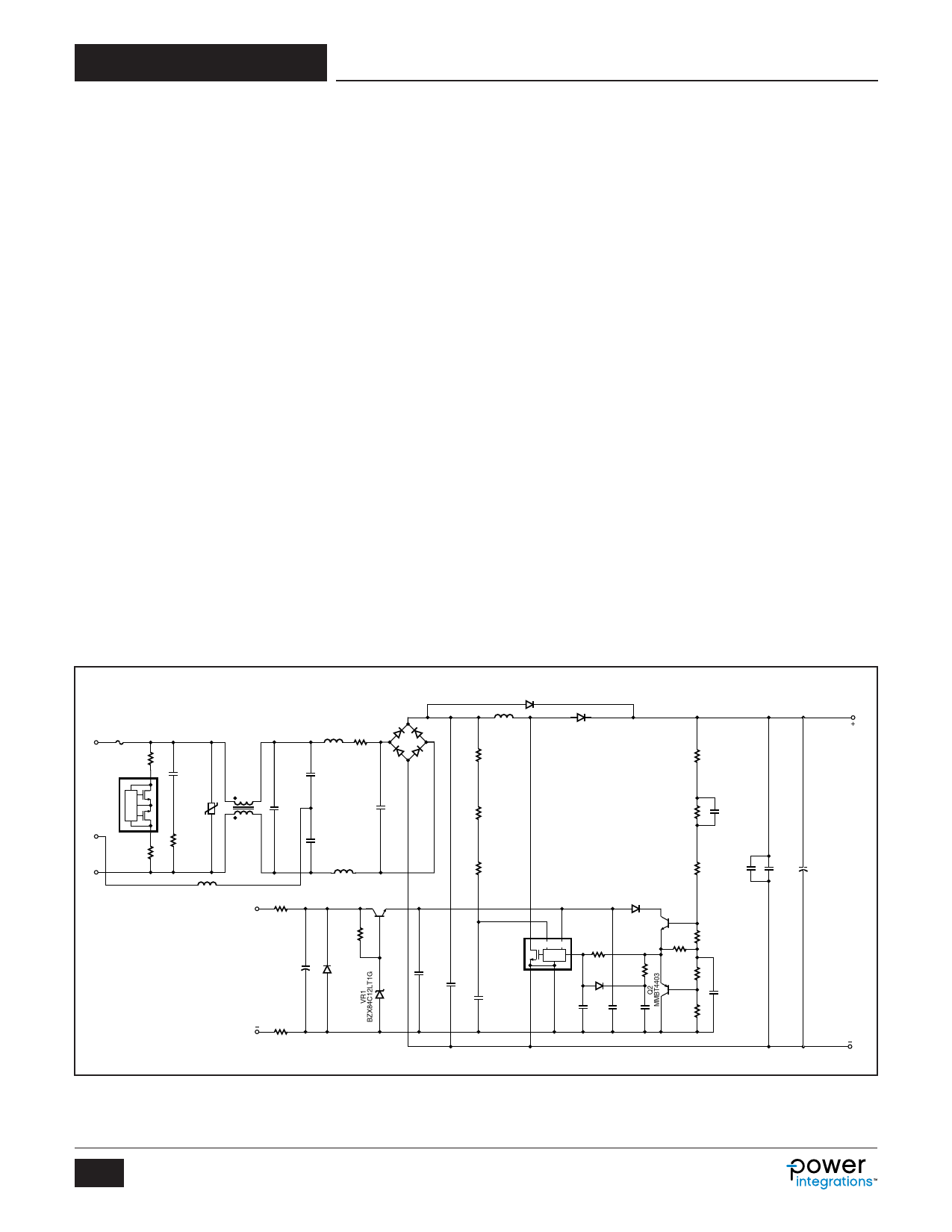
Application Example
A High Efficiency, 347 W, 380 VDC Universal Input PFC
The circuit shown in Figure 11 is designed using a PFS714EG
device from the HiperPFS family of integrated PFC controllers.
This design is rated for a continuous output power of 347 W
and provides a regulated output voltage of 380 VDC nominal
maintaining a high input power factor and overall efficiency from
light load to full load.
Fuse F1 provides protection to the circuit and isolates it from the
AC supply in case of a fault. Diode bridge BR1 rectifies the AC
input. Capacitors C3, C4, C5, C6 and C19 together with
inductors L1, L2, L3 and L4 form the EMI filter reducing the
common mode and differential mode noise. Resistors R1, R3
and CAPZero, IC U2 are required to discharge the EMI filter
capacitors once the circuit is disconnected. CAPZero
eliminates static losses in R1 and R2 by only connecting these
components across the input when AC is removed.
The boost converter stage consists of inductor L5, diode rectifier
D2 and the HiperPFS IC U1. This converter stage works as a
boost converter and controls the input current of the power
supply while simultaneously regulating the output DC voltage.
Diode D1 prevents a resonant build up of output voltage at start-
up by bypassing inductor L5 while simultaneously charging
output capacitor C15. Thermistor RT1 limits the inrush input
current of the circuit at start-up and prevents saturation of L5.
In most high-performance designs, a relay will be used to
bypass the thermistor after start-up to improve power supply
efficiency. Therefore efficiency measurement, that represents
the high performance configuration, the thermistors should be
shorted. Capacitors C14 and C21 are used for reducing the
loop length and area of the output circuit to reduce EMI and
overshoot of voltage across the drain and source of the
MOSFET inside U1 at each switching instant.
The PFS714EG IC requires a regulated supply of 12 V for
operation and must not exceed 15 V. Resistors R6, R16, R17,
Zener diode VR1, and transistor Q3 form a shunt regulator that
prevents the supply voltage to IC U1 from exceeding 12 V.
Capacitors C8, C18 and C20 filter the supply voltage and
provide decoupling to ensure reliable operation of IC U1. Diode
D5 prevents destruction of U1 if the auxiliary input is inadvertently
connected reverse polarity.
The rectified AC input voltage of the power supply is sensed by
IC U1 using resistors R4, R5 and R19. The capacitor C12 filters
any noise on this signal.
Divider network comprising of resistors R9, R10, R11, R12, R13,
and R14 are used to scale the output voltage and provide
feedback to IC U1. The circuit comprising of diode D4,
transistor Q1, Q2 and the resistors R12 and R13 form a non-
linear feedback circuit which improves the load transient
response by improving the response time of the PFC circuit.
Resistor R7, R8, R15, and capacitors C13 and C17 are required
for shaping the loop response of the feedback network. The
combination of resistor R8 and capacitor C13 provide a low
frequency zero and the resistor R15 and capacitor C13 form a
low frequency pole.
F1
6.3 A
L
R1
220 kΩ
D1
CAPZero
U2
CAP006DG
E
D2
R2
220 kΩ
N
C3
680 nF
275 VAC
RV1
320 VAC
R18
10 Ω
2W
L1
14 mH
C19
1 µF
310 V
L4
Ferrite Bead
R6
100 Ω
+
Auxiliary C8
Power 47 µF
Supply 50 V
L2
100 µH
BR1
RT1
10 Ω
GBU806
600 V
tO
C4
680 pF
250 VAC
C6
100 nF
275 VAC
C5
680 pF
250 VAC
L3
100 µH
Q3
MMBT4401LT1G
R17
3.01 kΩ
1%
D5
DL4001
R16
100 Ω
D1
1N5408
L5
1.38 mH
R4
1.5 MΩ
1%
D2
STTH8S06D
R9
1.5 MΩ
1%
R19
1.5 MΩ
1%
R11
732 kΩ
1%
C16
100 nF
200 V
R5
1 MΩ
1%
R10
1.6 MΩ
1%
C21
10 nF
1 kV
D4
1N4148
C20
100 nF
50 V
C7
1 µF
400 V
D
HiperPFS
U1
PFS714EG
S
C12
100 nF
50 V
V VCC
CONTROL
FB
R7
2 kΩ
Q1
MMBT4401
R15
160 kΩ
R12
2.21 kΩ
1%
D3
R8
G
BAV116 3.01 kΩ
130 V
1%
C11
10 nF
50 V
C18
1 µF
25 V
C13
4.7 µF
25 V
R13
2.21 kΩ
1%
R14
57.6 kΩ
1%
C17
470 pF
100 V
*Optional Component
Figure 11. 347 W PFC using PFS714EG.
380 VDC
C14
10 nF
1 kV
C15
270 µF
450 V
DC
OUT
PI-6197-111110
10
Rev. G 06/15
www.power.com
Share Link: 