AUIRG4PH50S Ver la hoja de datos (PDF) - International Rectifier
Número de pieza
componentes Descripción
Lista de partido
AUIRG4PH50S Datasheet PDF : 11 Pages
| |||
AUTOMOTIVE GRADE
PD -96301
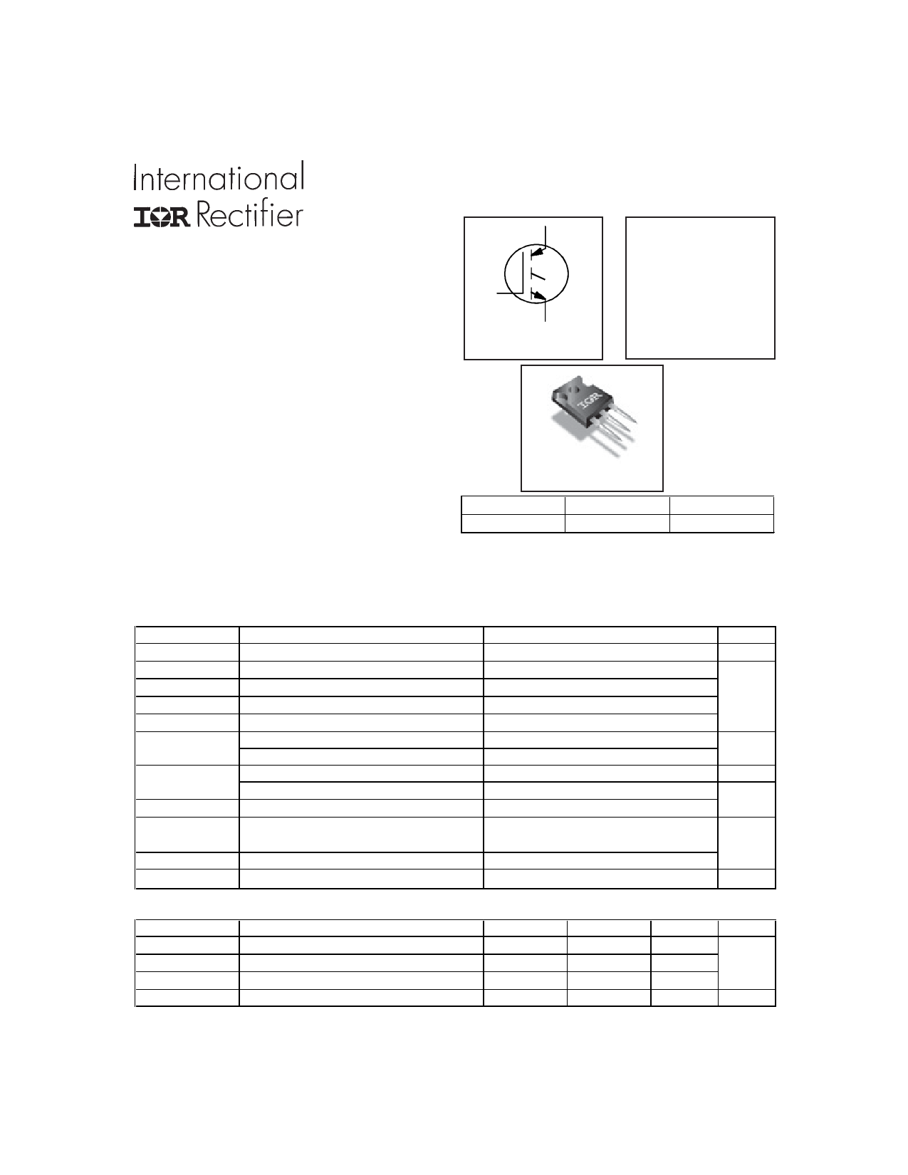
AUIRG4PH50S
Standard Speed IGBT
INSULATED GATE BIPOLAR TRANSISTOR
Features
Standard: Optimized for minimum saturation
voltage and low operating frequencies (< 1kHz)
Generation 4 IGBT design provides tighter
parameter distribution and higher efficiency
Industry standard TO-247AC package
Lead-Free
Automotive Qualified *
C
G
E
n-channel
C
VCES =1200V
VCE(on) typ. = 1.47V
@VGE = 15V, IC = 33A
Benefits
Generation 4 IGBT's offer highest efficiency available
IGBT's optimized for specified application conditions
E
C
G
TO-247AC
G
Gate
C
Collector
E
Emitter
Absolute Maximum Ratings
Stresses beyond those listed under “Absolute Maximum Ratings” may cause permanent damage to the device. These
are stress ratings only; and functional operation of the device at these or any other condition beyond those indicated in
the specifications is not implied.Exposure to absolute-maximum-rated conditions for extended periods may affect device
reliability. The thermal resistance and power dissipation ratings are measured under board mounted and still air conditions.
Ambient temperature (TA) is 25°C, unless otherwise specified.
Parameter
Max.
Units
VCES
Collector-to-Emitter Voltage
1200
V
IC@ TC = 25°C
IC@ TC = 100°C
ICM
ILM
VGE
EARV
Continuous Collector Current
Continuous Collector Current
c Pulsed Collector Current
d Clamped Inductive Load Current
Gate-to-Emitter Voltage
e Transient Gate-to-Emitter Voltage
Reverse Voltage Avalanche Energy
57
33
A
114
114
± 20
± 30
V
270
mJ
PD @ TC =25°
PD @ TC =100°
TJ
TSTG
Maximum Power Dissipation
Maximum Power Dissipation
Operating Junction and
Storage Temperature Range
Soldering Temperature, for 10 sec.
200
W
80
-55 to + 150
°C
300 (0.063 in. (1.6mm) from case)
Mounting Torque, 6-32 or M3 Screw.
10 lbf·in (1.1 N·m)
Thermal Resistance
Parameter
RθJC
RθCS
RθJA
Wt
Junction-to-Case
Case-to-Sink, Flat, Greased Surface
Junction-to-Ambient, typical socket mount
Weight
Min.
—
—
—
—
Typ.
—
0.24
—
6.0(0.21)
Max.
0.64
—
40
—
Units
°C/W
g (oz)
www.irf.com
1
04/13/10
Share Link: 