IMIFS741 Ver la hoja de datos (PDF) - Unspecified
Número de pieza
componentes Descripción
Lista de partido
IMIFS741 Datasheet PDF : 16 Pages
| |||
Approved Product
FS741
Low EMI Spectrum Spread Clock
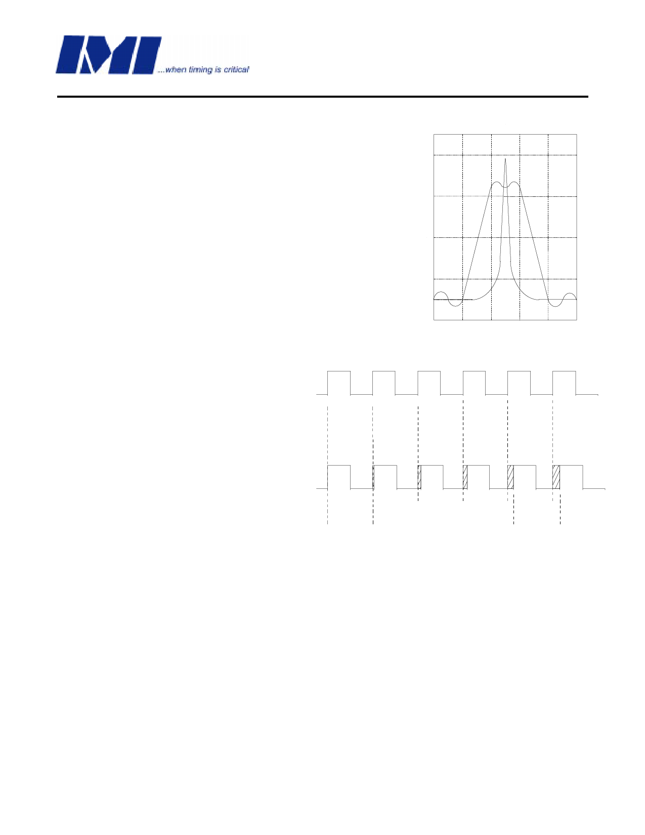
We see that the original 20 MHz reference clock is at the center Frequency,
Fc, and the minimum and maximum extremes are positioned symmetrically
about the center frequency. This type of modulation is called Center-
Spread. Figure 7 illustrates this as it is seen on a spectrum analyzer.
Fc = 20 MHz
Fmin =
19.8 MHz
Fmax =
20.2 MHz
Figure 7.
Figure 8 shows a 20 MHz clock as it would be seen
on an oscilloscope. The top trace is the non-
modulated reference clock, or the Refout clock at pin
7. The bottom trace is the modulated clock at pin 6.
From this comparison chart you can see that the
frequency is decreasing and the period of each
successive clock increasing. The Tc measurements
on the left and right of the bottom trace indicate the
max. and min. extremes of the clock. Intermediate
clock changes are small and accumulate to achieve
the total period deviation. The reverse of this Figure
would show the clock going from min. extreme back
to the high extreme.
Tc =49.50 ns.
Tc = 50.50 ns.
Figure 8. Period Comparison Chart
The FS741 is a center spread clock, meaning that it symetrically spreads above and below the reference
frequency. If a down spread clock is required for a specific application, refer to the datasheets for the SM530 and
the SG52x series of Low EMI clock generators.
Looking at figure 7, you will note that the peak amplitude of the 20 MHz non-modulated clock is higher than the
wideband modulated clock. This difference in peak amplitudes between modulated and unmodulated clocks is the
reason why SSCG clocks are so effective in digital systems. This figure refers to the fundamental frequency of a
clock. A very important characteristic of the SSCG clock is that the bandwidth of the harmonics is multiplied by the
harmonic number. In other words, if the bandwidth of a 20 MHz clock is 200 KHz, the bandwidth of the 3rd
harmonic will be 3 times 200 KHz, or 600 KHz. The amount of bandwidth is relative to the amount of energy in the
clock. Consequently, the wider the bandwidth, the greater the energy reduction of the clock.
International Microcircuits, Inc.
525 Los Coches St., Milpitas, 95035 408-263-6300, FAX 408-263-6571
http:/www.imicorp.com
4/5/1999
Rev. 2.1
Page 11 of 16
Share Link: 