GS-R51212 Ver la hoja de datos (PDF) - STMicroelectronics
Número de pieza
componentes Descripción
Lista de partido
GS-R51212 Datasheet PDF : 5 Pages
| |||
GS-R51212
USER NOTES
Input Voltage
The recommended operating maximum DC input
voltage is 40V inclusive of the ripple voltage.
Case Grounding
The module case is internally connected to pin 2
and pin 8.
The PCB area below the module can be used as
an effective sixth side shield against EMI.
Thermal Characteristics
The case-to-ambient thermal resistance of the
GS-R51212 module is about 5°C/W. This produces
a 50°C temperature increase of the module surface
for a 10W of internal power dissipation.
Depending on the ambient temperature and/or on
the power dissipation, an additional heatsink or
forced ventilation may be required.
Input Impedance
The module has an internal capacitor connected
between the input pins in order to assure PWM
stability. This capacitor cannot handle large values
of high frequency ripple current, and it can be
permanently damaged if the primary energy source
impedance is not adequate.
The use of an external low ESR, high ripple current
capacitor located as close to the module as possi-
ble is recommended. Suitable capacitors should
have a RMS current capability of 2,5 ARMS with a
working voltage of 50 VDC and an ESR of 0,1Ω at
100 kHZ. When space is a limitation, a 22µF ce-
ramic multilayer capacitor must be connected to the
module input pins.
Module Protection
The module is protected against occasional and
permanent short circuits of the output pins to
ground, as well as against output current overload.
When the output current at 5V output exceeds the
maximum value, the output is automatically dis-
abled. After a fixed time the module starts again in
a soft mode. The cycle is repeated until the overload
condition is removed.
A crow-bar output overvoltage protection is acti-
vated when the output voltage on Vo1 exceeds
6.37V.
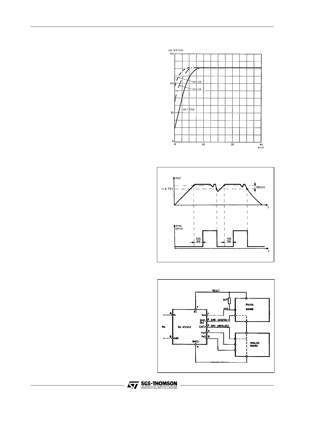
Output Current
The output current of the main output is 3.5A. The
max output current of the two 12V outputs is a
function of the input voltage and of the main output
current as shown in fig. 1.
If the main current is zero, no voltage will be avail-
able on the 12V outputs.
4/5
Figure 1. Output Current Capability vs. Operat-
ing Conditions
Figure 2. Reset Operation
Figure 3. Typical application
Share Link: 