74VHCT574A Ver la hoja de datos (PDF) - STMicroelectronics
Número de pieza
componentes Descripción
Lista de partido
74VHCT574A Datasheet PDF : 13 Pages
| |||
74VHCT574A
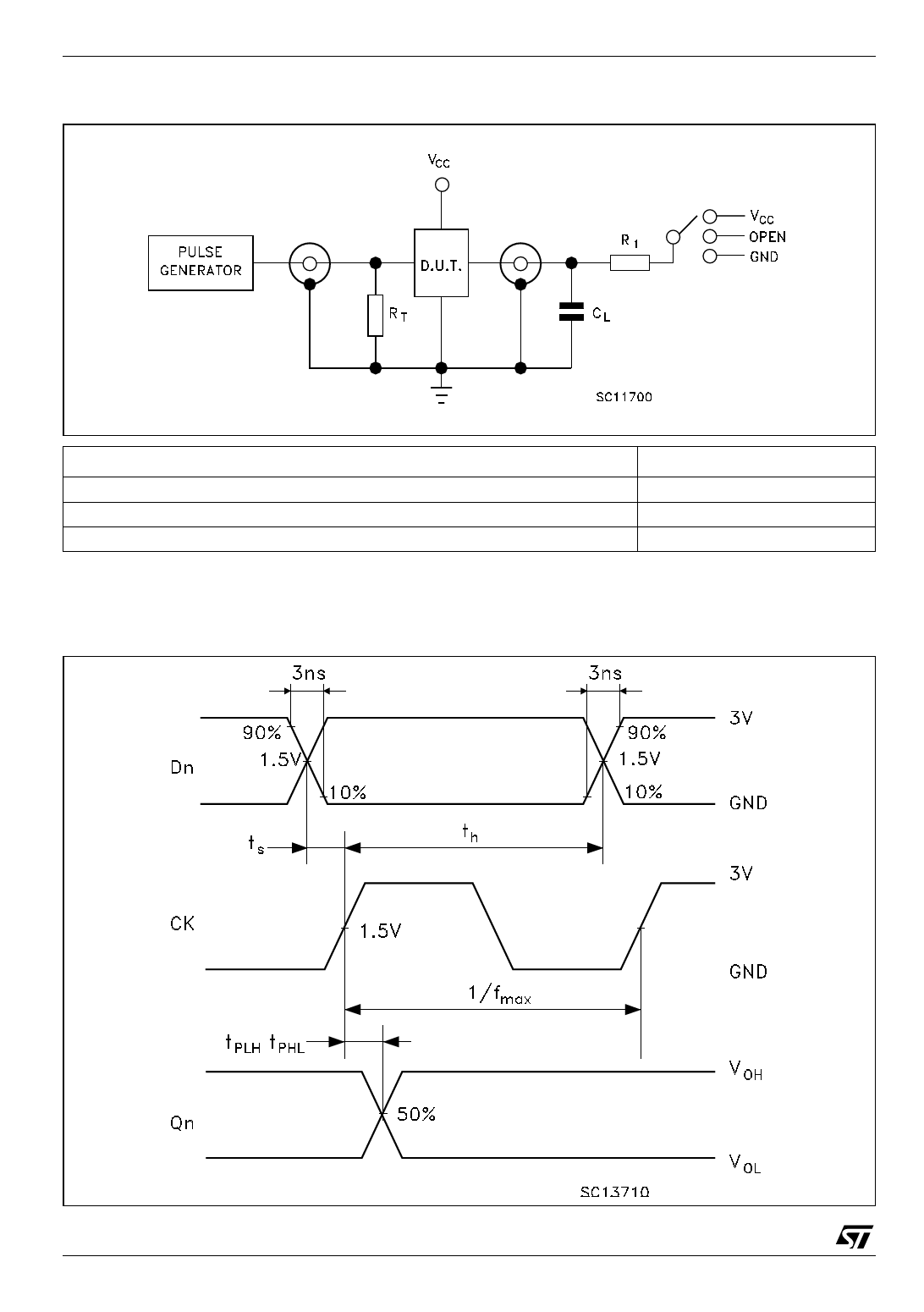
Figure 4: Test Circuit
tPLH, tPHL
tPZL, tPLZ
tPZH, tPHZ
TEST
SWITCH
Open
VCC
GND
CL =15/50pF or equivalent (includes jig and probe capacitance)
RL = R1 = 1KΩ or equivalent
RT = ZOUT of pulse generator (typically 50Ω)
Figure 5: Waveform - Propagation Delays, Setup And Hold Times (f=1MHz; 50% duty cycle)
6/13
Share Link: 