A29DL323UV-90(2002) Ver la hoja de datos (PDF) - AMIC Technology
Número de pieza
componentes Descripción
Lista de partido
A29DL323UV-90
(Rev.:2002)
(Rev.:2002)
AMIC Technology

A29DL323UV-90 Datasheet PDF : 46 Pages
| |||
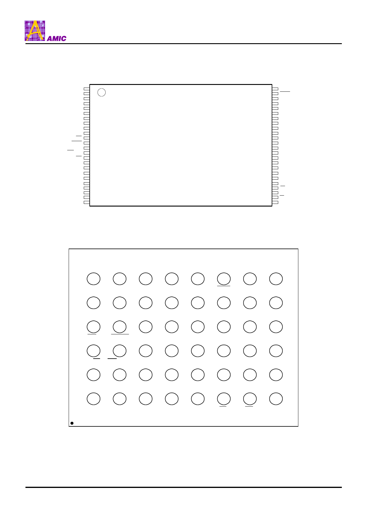
A29DL323 Series
Input / Output Pin Function
Pin Name
A0 to A20
I/O0 to I/O14
I/O15, A-1
CE
OE
WE
BYTE
RESET
RY/ BY
WP (ACC)
VCC
GND
NC
Input / Output
Input
Input / Output
Input / Output
Input
Input
Input
Input
Input
Output
Input
-
-
-
Function
Address input pins.
A0 to A20 are used differently in the BYTE mode and the WORD mode.
BYTE MODE
A0 to A20 are used as the upper 21 bits of total 22 bits of address input pin.
(The least significant bit (A-1) is combined to I/O15.)
WORD MODE
A0 to A20 are used as 21 bits address input pin.
Data input / output pins.
I/O0 to I/O14 are used differently in the BYTE mode and the WORD mode.
BYTE MODE
I/O0 to I/O7 are used as the 8 bits data input / output pins.
I/O8 to I/O14 are Hi-Z.
WORD MODE
I/O0 to I/O14 are used as the lower 15 bits of total 16 bits of data input / output pins.
(The most significant bit (I/O15) is combined to A-1.)
I/O15, A1 are used differently in the BYTE mode and the WORD mode.
BYTE MODE
The least significant address input pin (A-1)
WORD MODE
The most significant data input / output pin (I/O15)
This pin inputs the signal that activates the chip.
When high level, the chip enters the standby mode.
This pin inputs the read operation control signal.
When high level, output is Hi-Z.
This pin inputs the write operation control signal.
When low level, command input is accepted.
The pin for switching BYTE mode and WORD mode.
High level : WORD MODE (2M words x 16 bits)
Low level : BYTE MODE (4M words x 8 bits)
This pin inputs hardware reset.
When low level, hardware reset is performed.
If 11.5 to 12.5 V is applied to RESET , the chip enters the temporary sector group
unprotect mode.
This pin indicates whether automatic program / erase is currently being executed. It uses
open drain connection.
Low level indicates the busy state during which the device is performing automatic
program erase.
High level indicates the device is in the ready state and will accept the next operation. In
this case, the device is either in the erase suspend mode or the standby mode.
This pin selects the boot block sector protect mode or accelerated mode.
Low level: The boot block (2 sectors) is protected.
High level: The boot block is unprotected.
VACC level: Accelerated mode is selected.
Supply Voltage
Ground
No Connection
PRELIMINARY (May, 2002, Version 0.0)
4
AMIC Technology, Inc.
Share Link: