A29L004AUY-70F Ver la hoja de datos (PDF) - AMIC Technology
Número de pieza
componentes Descripción
Lista de partido
A29L004AUY-70F Datasheet PDF : 39 Pages
| |||
A29L004A Series
Table 6. Write Operation Status
Operation
Standard
Mode
Erase
Suspend
Mode
Embedded Program Algorithm
Embedded Erase Algorithm
Reading within Erase
Suspended Sector
Reading within Non-Erase
Suspended Sector
Erase-Suspend-Program
I/O7
I/O6
I/O5
I/O3
I/O2
(Note 1)
(Note 2)
(Note 1)
I/O 7
0
1
Data
I/O 7
Toggle
Toggle
No
toggle
Data
Toggle
0
0
0
Data
0
N/A
No
toggle
1 Toggle
N/A Toggle
Data
N/A
Data
N/A
RY/ BY
(N/A on 32-pin PLCC
& (s)TSOP packages)
0
0
1
1
0
Notes:
1. I/O7 and I/O2 require a valid address when reading status information. Refer to the appropriate subsection for further details.
2. I/O5 switches to “1” when an Embedded Program or Embedded Erase operation has exceeded the maximum timing limits.
See “I/O5: Exceeded Timing Limits” for more information.
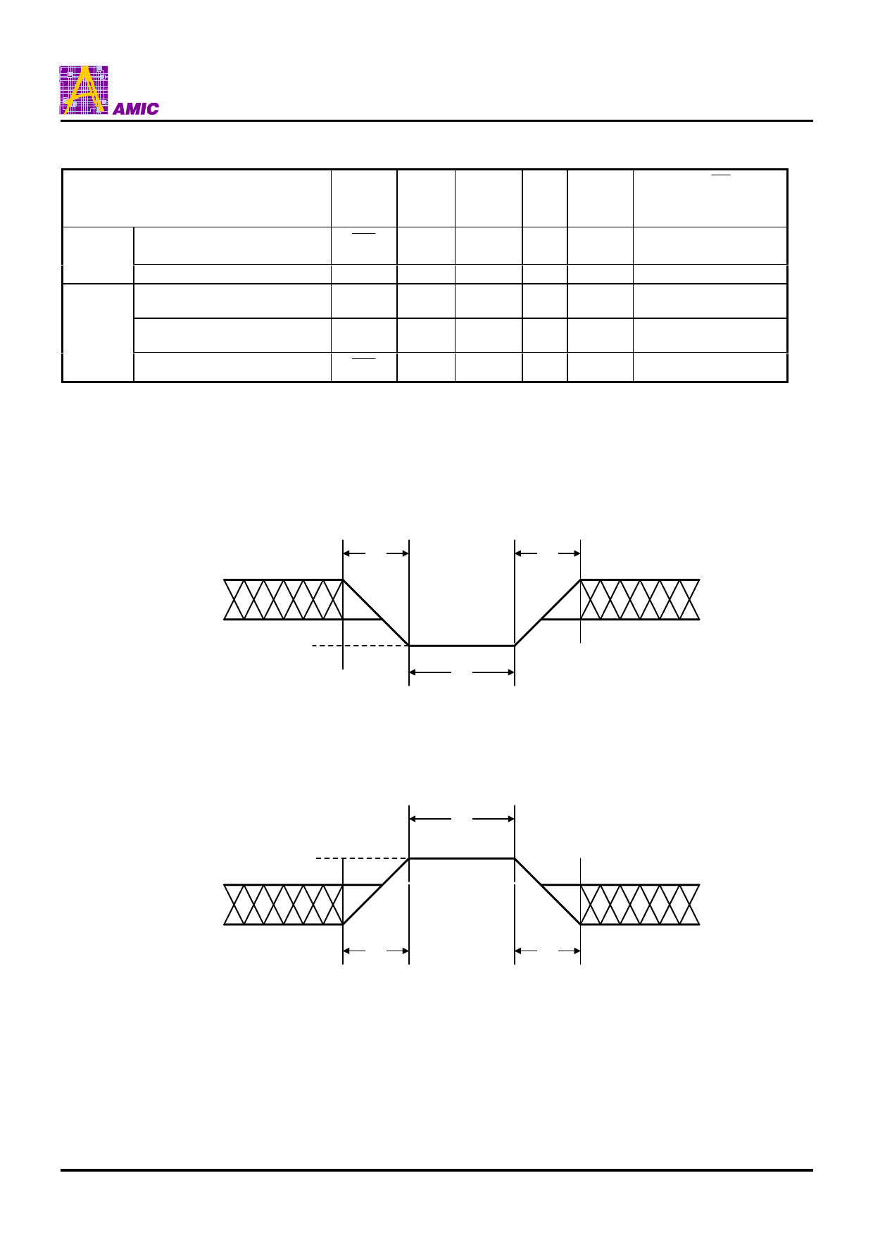
Maximum Negative Input Overshoot
+0.8V
-0.5V
20ns
20ns
-2.0V
20ns
Maximum Positive Input Overshoot
VCC+0.5V
2.0V
VCC+2.0V
20ns
20ns
20ns
PRELIMINARY (March, 2005, Version 0.0)
17
AMIC Technology, Corp.
Share Link: 