A29L040A-70 Ver la hoja de datos (PDF) - AMIC Technology
Número de pieza
componentes Descripción
Lista de partido
A29L040A-70 Datasheet PDF : 30 Pages
| |||
A29L040A Series
Autoselect Mode
The autoselect mode provides manufacturer and device
identification, and sector protection verification, through
identifier codes output on I/O7 - I/O0. This mode is primarily
intended for programming equipment to automatically match
a device to be programmed with its corresponding
programming algorithm. However, the autoselect codes can
also be accessed in-system through the command register.
When using programming equipment, the autoselect mode
requires VID (11.5V to 12.5 V) on address pinA9. Address
pins A6, A1, and AO must be as shown in Autoselect Codes
(High Voltage Method) table. In addition, when verifying
sector protection, the sector address must appear on the
appropriate highest order address bits. Refer to the
corresponding Sector Address Tables. The Command
Definitions table shows the remaining address bits that are
don't care. When all necessary bits have been set as
required, the programming equipment may then read the
corresponding identifier code on I/O7 - I/O0.To access the
autoselect codes in-system, the host system can issue the
autoselect command via the command register, as shown in
the Command Definitions table. This method does not
require VID. See "Command Definitions" for details on using
the autoselect mode.
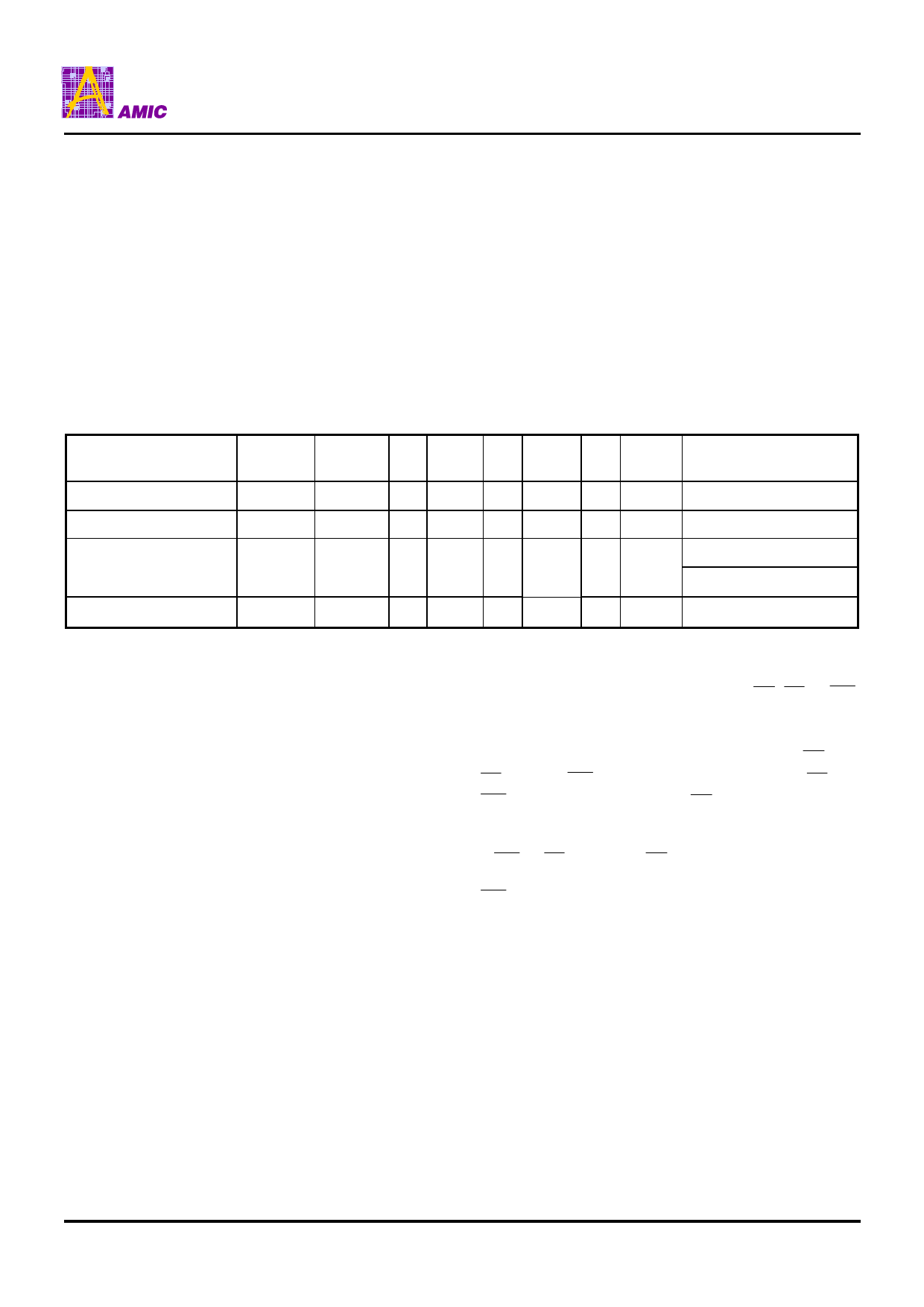
Table 3. A29L040A Autoselect Codes (High Voltage Method)
Description
Manufacturer ID: AMIC
Device ID: A29L040A
Sector Protection
Verification
A18 - A16 A15 - A10 A9 A8 - A7 A6 A5 - A2 A1 AO
X
X
Sector
Address
X
VID
X
VIL
X
VIL VIL
X
VID
X
VIL
X
VIL VIH
X
VID
X
VIL
X
VIH VIL
Continuation ID
X
X
VID
X
VIL
X
VIH
VIH
Identifier Code on
I/O7 - I/O0
37h
92h
01h (protected)
00h (unprotected)
7Fh
Sector Protection/Unprotection
The hardware sector protection feature disables both
program and erase operations in any sector. The hardware
sector unprotection feature re-enables both program and
erase operations in previously protected sectors.
Sector protection/unprotection must be implemented using
programming equipment. The procedure requires a high
voltage (VID) on address pin A9 and the control pins.
The device is shipped with all sectors unprotected.
It is possible to determine whether a sector is protected or
unprotected. See "Autoselect Mode" for details.
Hardware Data Protection
The requirement of command unlocking sequence for
programming or erasing provides data protection against
inadvertent writes (refer to the Command Definitions table).
In addition, the following hardware data protection measures
prevent accidental erasure or programming, which might
otherwise be caused by spurious system level signals during
VCC power-up transitions, or from system noise. The device
is powered up to read array data to avoid accidentally writing
data to the array.
Write Pulse "Glitch" Protection
Noise pulses of less than 5ns (typical) on OE , CE or WE
do not initiate a write cycle.
Logical Inhibit
Write cycles are inhibited by holding any one of OE =VIL,
CE = VIH or WE = VIH. To initiate a write cycle, CE and
WE must be a logical zero while OE is a logical one.
Power-Up Write Inhibit
If WE = CE = VIL and OE = VIH during power up, the
device does not accept commands on the rising edge of
WE . The internal state machine is automatically reset to
reading array data on the initial power-up.
PRELIMINARY (March, 2005, Version 0.0)
6
AMIC Technology, Corp.
Share Link: 