AIC1647 Ver la hoja de datos (PDF) - Analog Intergrations
Número de pieza
componentes Descripción
Lista de partido
AIC1647 Datasheet PDF : 11 Pages
| |||
AIC1647
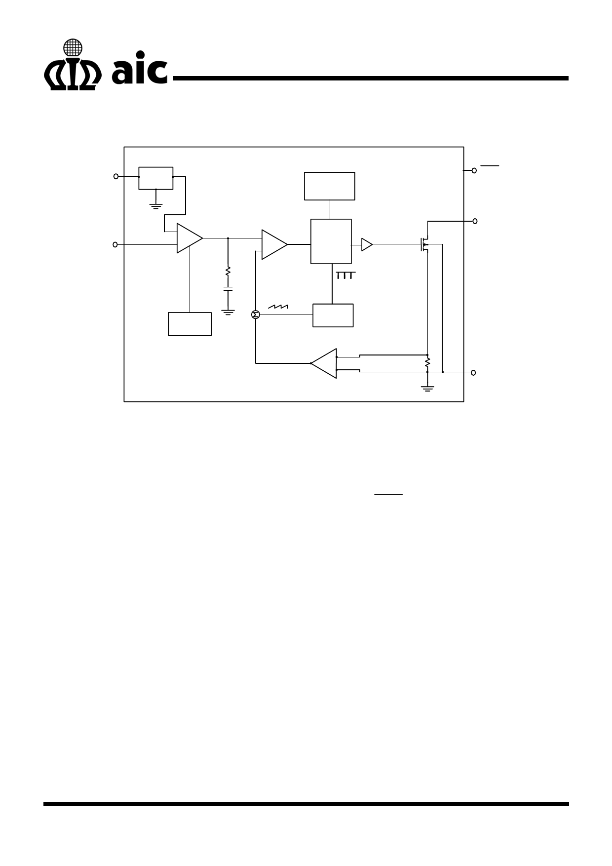
BLOCK DIAGRAM
VIN
95mV
VREF
PWM/PFM
Control
Error
FB
+ AMP.
-
+
Control
Driver
M1
Logic
-
PWM
RC Comparator
Internal
Soft Start
CC
Slope
1.2MHz
Compensation Oscillator
Current AMP
+
RS
-
SHDN
SW
GND
PIN DESCRIPTIONS
PIN 1: SW
PIN 2: GND
- Switch
Pin.
Connect
inductor/diode here. Minimize
trace area at this pin to reduce
EMI.
- Ground Pin. Tie directly to local
ground plane.
PIN 3: FB
- Feedback Pin. Reference
voltage is 95mV. Connect
cathode of lowest LED and
resistor here. Calculate resistor
value according to the formula:
RFB = 95mV/ILED
PIN 4: SHDN - Shutdown pin. Tie to higher than
1.5V to enable device, 0.3V or
less to disable device.
PIN 5: VIN
- Power input pin. Bypass VIN to
GND with a capacitor sitting as
close to VIN as possible.
7
Share Link: 