BA6438 Ver la hoja de datos (PDF) - ROHM Semiconductor
Número de pieza
componentes Descripción
Lista de partido
BA6438 Datasheet PDF : 8 Pages
| |||
Motor driver ICs
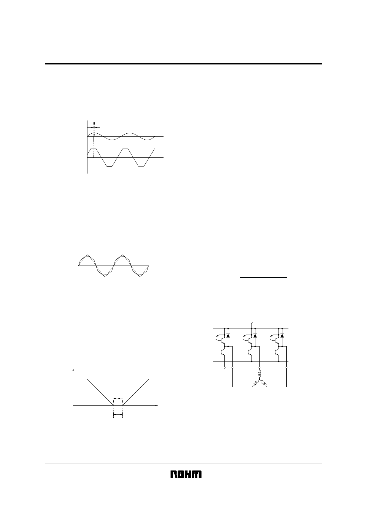
!Circuit operation
(1) Pseudo-linear output and torque ripple cancellation
The IC generates a trapezoidal (pseudo-linear) output
current, whose waveform phase is 30 degrees ahead of
that of the Hall input voltage (Fig. 1).
.
30°
Hall input
Output current
Fig. 1
The trapezoidal waveform of output current would create
intermittence in the magnetic field generated by the 3-
phase motor, and would result in an irregular rotation of
the motor. To prevent this, the output waveform is ob-
tained by superimposing a triangular wave on the trape-
zoidal wave (Fig. 2). This process is called torque ripple
cancellation.
BA6438S
A brake is applied to the motor as described in the
following.When the motor is running, pin 17 is given a
negative potential with respect to the reference potential. If
the pin 17 potential becomes positive, the IC detects the
rise of pin 17 potential above the reference potential and
activates the motor direction detecting circuit.
The motor direction detecting circuit sends a signal to the
motor direction setting circuit to reverse the motor direc-
tion. This causes a braking torque that depends on the
pin 17 potential, so that the motor quickly reduces its
speed. At the same time, the positive pin 17 potential is
shifted to the reference potential, so that the motor stops
smoothly.
(3) Output current sensing and torque limitation
Pin 2 is the ground pin for the output stage. To sense the
output current, a resistor (0.5Ω recommended) is con-
nected between pin 2 and the ground. The output current
is sensed by applying the voltage developed across this
resistor to pin 22 as a feedback.
The output current can be limited by adjusting the voltage
applied to pin 20. The current is limited when pin 20
reaches the same potential as pin 22. The output current
(IMAX. ) under this condition is given by:
Fig. 2
(2) Torque control and reversal brake
The output current can be controlled by adjusting the
voltage applied to the torque control pins (pins 16 and 17).
These pins are the inputs to a differential amplifier. A ref-
erence voltage between 2.3 ~ 3.0V (2.5V recommended)
is applied to pin 16.
IMAX.=
V20P(TL−CSofs)
R2P
where R2P is the value of the resistor connected between
pin 2 and the ground, V20P is the voltage applied to pin 20,
and (TL–CSofs ) is the offset between the TL and CS pins.
VM
24pin
Output current
Pin 16
reference voltage (2.5 V)
1pin
3pin
23pin
ATC
2pin
Offset
0
Pin 17 voltage
Dead zone (100 mV typically)
Fig. 3
Fig.4 Output circuit
Share Link: 