BA6458 Ver la hoja de datos (PDF) - ROHM Semiconductor
Número de pieza
componentes Descripción
Lista de partido
BA6458 Datasheet PDF : 8 Pages
| |||
Motor driver ICs
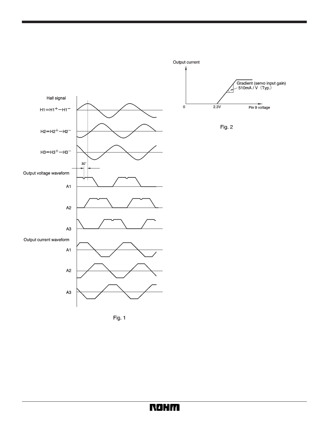
FCircuit operation
(1) The 3-phase Hall signal is amplified in the hall am-
plifiers and sent to the matrix section, where the signal is
further amplified and combined. After the signal is con-
verted to a current in the amplitude control circuit, the cur-
rent is supplied to the output driver, which then provides
a motor drive current. The phases of the Hall input signal,
output voltage, and output current are shown in Fig. 1.
BA6458FP-Y
(2) Torque control pin
The output current can be controlled by adjusting the
voltage applied to the torque control pin (pin 9).
(3) Start / stop pin
The motor is in the run mode when the pin input voltage
is 3.5V or more and in the idle mode (all output transistors
are off) when the voltage is 1.2V or less.
(4) Power ground pin (RNF pin)
The RNF pin is the output stage ground pin. Connect a re-
sistor (0.5Ω recommended) between this pin and the
ground to monitor the output current.
(5) Torque limit pin (TL pin)
The output current can be limited by applying a voltage
to the torque limit pin. Control is provided so that this pin
will have the same potential as the RNF pin. Note that
there is an offset in the TL-pin voltage.
(6) Phase compensation pin (CNF pin)
Connect a capacitor between this pin and VCC if the out-
put tends to oscillate.
(7) Amplifiers 1 and 2
Amplifiers 1 and 2 have an open loop gain of about 70dB
(typical). The input terminals are biased internally to
2.45V (typical).
(8) Hysteresis amplifiers
The hysteresis amplifiers have a hysteresis width of
±120mV (typical). The input terminals are biased inter-
nally.
606
Share Link: 