BU9480 Ver la hoja de datos (PDF) - ROHM Semiconductor
Número de pieza
componentes Descripción
Lista de partido
BU9480 Datasheet PDF : 5 Pages
| |||
Multimedia ICs
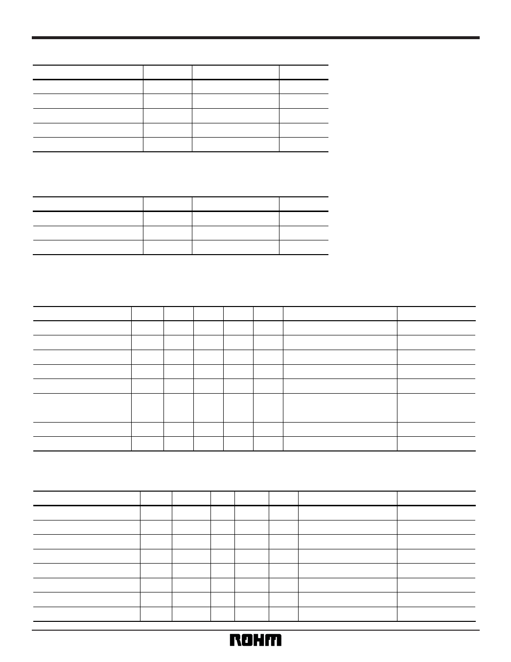
•Absolute maximum ratings (Ta = 25°C)
Parameter
Symbol
Limits
Unit
Applied voltage
Power dissipation
VDDMax.
Pd
7.0
450∗
V
mW
Operating temperature
Storage temperature
Topr
Tstg
– 10 ~ + 70
°C
– 55 ~ + 125
°C
Input voltage
Topt
– 0.3 ~ VDD + 0.3
V
∗ When unmounted, reduced by 4.5mW for each increase in Ta of 1°C over 25°C.
•Recommended operating conditions
Parameter
Symbol
Limits
Unit
Power supply voltage
VDD
3.0 ~ 5.5
V
Input low level voltage
VIL
0.0 ~ 0.2 × VDD
V
Input high level voltage
VIH
0.8 × VDD ~ VDD
V
BU9480F
•Electrical characteristics (unless otherwise noted, Ta = 25°C, VDD = + 5.0V)
Analog unit characteristics
Parameter
Current dissipation
Resolution
Noise distortion 1
Noise distortion 2
Full-scale output voltage
Symbol Min.
IDD
—
RES —
THD1 —
THD2 —
VFS
1.8
Typ. Max.
3.6
6
—
16
0.05 0.12
0.07 0.4
2
2.2
Crosstalk
C.T
— – 92 – 85
S / N ratio
S / N 86
93
—
Output pin load resistance RL
10
—
—
Unit
Conditions
mA f = 1kHz, 0dB
BIT
—
% f = 1kHz, 0dB
% f = 1kHz, – 20dB
VP-P
—
Measurement circuit
Fig.6,7
Fig.6,7
Fig.6,7
Fig.6,7
Fig.6,7
dB
Unmeasured channel output =
0 dB, f = 1kHz. DIN audio filter
Fig.6,7
dB DIN audio filter
kΩ
—
Fig.6,7
Fig.6,7
Logic input characteristics
Parameter
Input high level voltage
Input low level voltage
Leakage current, high level
Leakage current, low level
DA conversion frequency
BCLK period
SDAT.LRCK settling time
SDAT.LRCK holding time
Symbol Min. Typ. Max. Unit
VIH 0.7 × VDD —
VDD
V
VIL
GND
— 0.3 × VDD V
IIH
—
— – 10
µA
IIL
—
—
10
µA
fSL
—
—
200
kHZ
TBCLK
60
—
—
ns
TST
60
—
—
ns
THD
60
—
—
ns
Conditions
Pins 5,6 and 7
Pins 5,6 and 7
Pins 5,6 and 7 = VDD
Pins 5,6 and 7 = GND
—
—
—
—
2
Measurement circuit
Fig.6,7
Fig.6,7
Fig.6,7
Fig.6,7
Fig.6,7
Fig.6,7
Fig.6,7
Fig.6,7
Share Link: 