ST735S Ver la hoja de datos (PDF) - STMicroelectronics
Número de pieza
componentes Descripción
Lista de partido
ST735S Datasheet PDF : 11 Pages
| |||
ORDERING CODES
TYPE
ST735S
ST735T
DIP-8
ST735SCN
ST735TCN
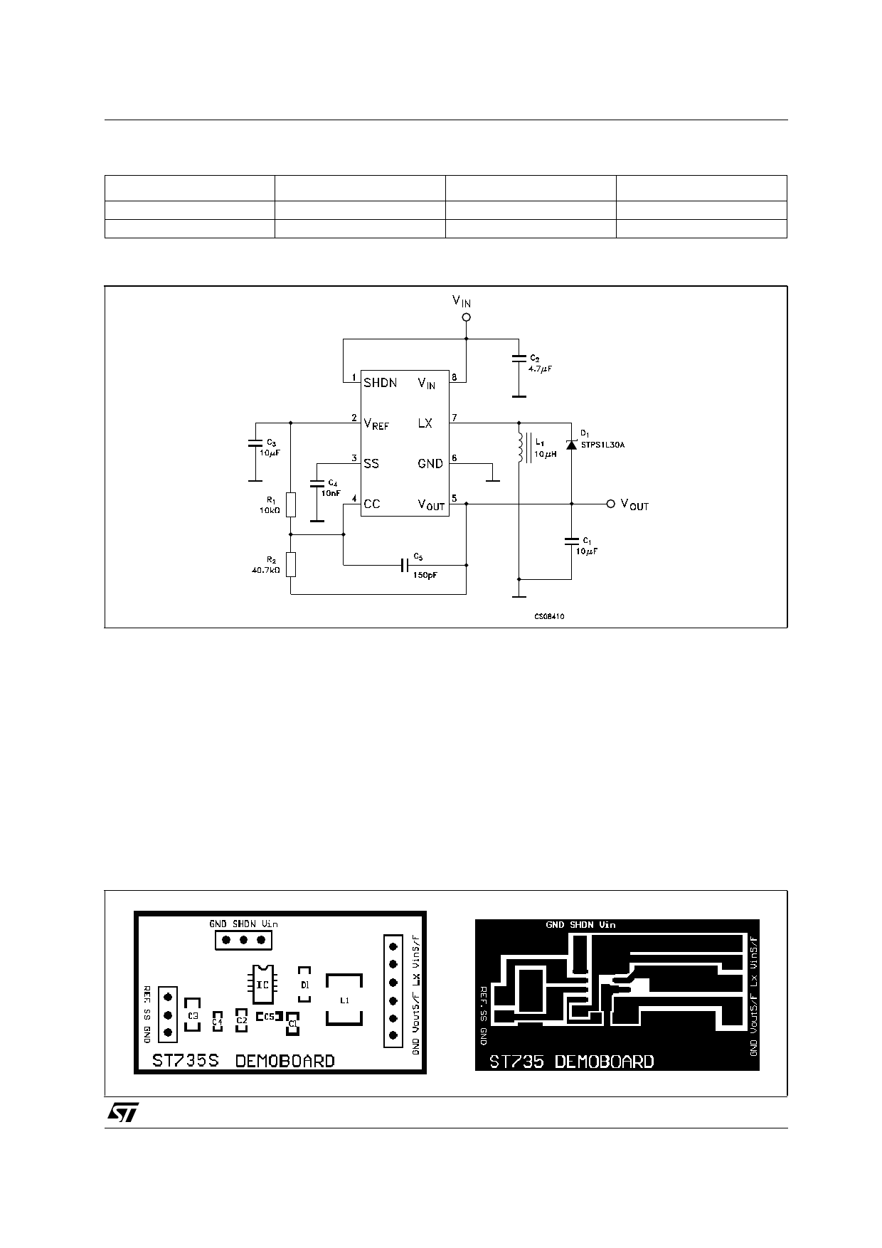
TYPICAL APPLICATION CIRCUIT
SO-8
ST735SCD
ST735TCD
ST735S/ST735T
SO-8 (T&R)
ST735SCD-TR
ST735TCD-TR
NOTE:
1) All capacitors are X7R ceramic
2) C5 can be omitted if are used higher values for the input and output capacitors (suggested C2=47µF, C1=100µF).
3) R1 and R2 must be placed is ST735T applications only. Their values are calculated by the following formula R2=(|VOUT|/VREF)xR1. For R1
can be chosen any value between 2kΩ and 20kΩ
APPLICATION CIRCUIT
To achieve the best performances from switching
power supply topology, particular care to layout
drawing is needed, in order to minimize EMI and
obtain low noise. Moreover, jitter free operation
ensures the full device functionality. Layout design
proposed on demoboard helps to lower the
developing time. Wire lengths must be minimized,
filter and bypass capacitors must be low ESR
type, placed as close as possible to the integrated
circuit. The 4.7µF (or 6.8µF) inductor must be
chosen built on a core, taking care that saturation
current should be higher than the peak LX switch
current. See the Peak Inductor Current vs Output
Current graph.
PRINTED DEMOBOARD (not in scale)
3/11
Share Link: 