CS1601-FSZR Ver la hoja de datos (PDF) - Cirrus Logic
Número de pieza
componentes Descripción
Lista de partido
CS1601-FSZR Datasheet PDF : 16 Pages
| |||
CS1601
5.5 PFC Output Capacitor
The value of the PFC output capacitor needs to be selected
based upon voltage ripple and hold-up requirements. To
ensure system stability with the digital controller, the
recommended value of the capacitor is within the range of
0.25F/watt to 0.5F/watt with a Vlink voltage of 460V.
5.6 Output IFB Sense and Input IAC Sense
A current proportional to the PFC output voltage, Vlink, is
supplied to the IC on pin IFB and is used as a feedback control
signal. This current is compared against an internal fixed-
value reference current.
The ADC is used to measure the magnitude of the IIFB current
through resistor RIFB. The magnitude of the IIFB current is then
compared to an internal reference current of (Iref) 129A.
V link
R5
IFB
R IFB
VDD
R6
8
CS1601
15 k
IFB
1
24 k
AD C
Figure 17. IFB Input Pin Model
Resistor RIFB sets the feedback current and is calculated as
follows:
RIFB = V-----l-i--n--k-I--r-–-e---f-V----D----D-- = 4----6---01----2V---9--–-----VA----D----D--
[Eq.4]
By using digital loop compensation, the voltage feedback
signal does not require an external compensation network.
A current proportional to the AC input voltage is supplied to the
IC on pin IAC and is used by the PFC control algorithm.
V rect
R1
IAC
R IAC
VDD
R2
8
CS1601
15 k
IA C
3
24 k
AD C
Figure 18. IAC Input Pin Model
Resistor RIAC sets the IAC current and is derived as follows:
RIAC = RIFB
[Eq.5]
For optimal performance, resistors RIAC and RIFB should use
1% tolerance or better resistors for best Vlink voltage accuracy.
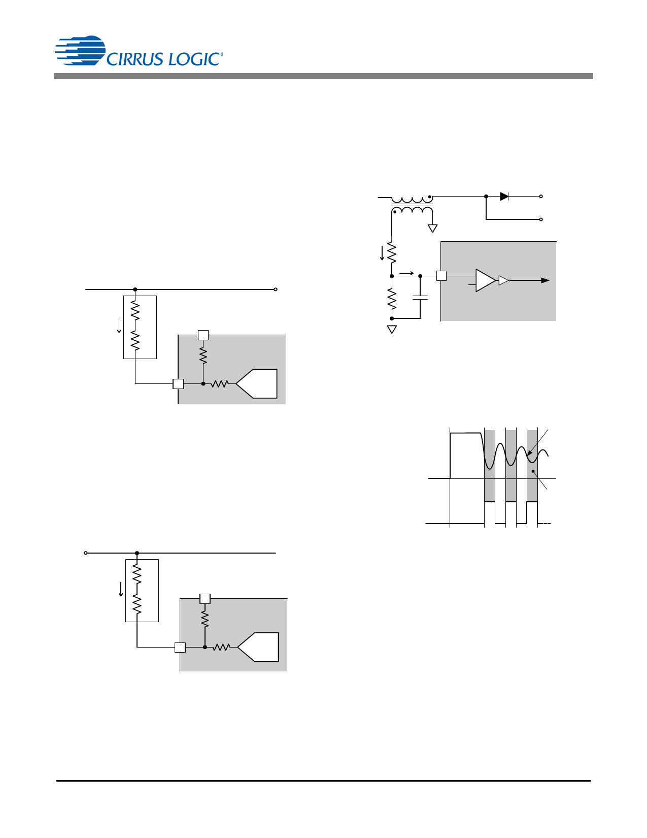
5.7 Valley Switching
The zero-current detection (ZCD) pin is monitored for
demagnetization in the auxiliary winding of the boost inductor
(LB). The ZCD circuit is designed to detect the VAux
valley/zero crossings by sensing the voltage transformed onto
the auxiliary winding of LB.
LB
N :1
Vlink
D2
FE T Drain
IAux
R3
IZ CD
+
VAux R4
-
CS1601
5
ZC D
Cp
+
- Vth( Z CD)
D emag
C o mp a r a to r
ZC D _ be low_ z e r o
Figure 19. ZCD Input Pin Model
The objective of zero-voltage switching is to initiate each
MOSFET switching cycle when its drain-source voltage is at
the lowest possible voltage potential, thus reducing switching
losses. The CS1601 uses an auxiliary winding on the PFC
boost inductor to implement zero-voltage switching.
Zero Crossing
Detection
ZCD
ZCD_below _zero
GD ‘ON’
Figure 20. Zero-voltage Switch
During each switching cycle, when the boost diode current
reaches zero, the boost MOSFET drain-source voltage begins
oscillating at the resonant frequency of the boost inductor and
MOSFET parasitic output capacitance. The ZCD_below_zero
signal transitions from high to low just prior to a local minimum
of the MOSFET drain-source voltage oscillation. The zero-
crossing detect circuit ensures that a ZCD_below_zero pulse
will only be generated when the comparator output is
continuously high for a nominal time period (tZCB) of 200ns.
Therefore, any negative edges on the comparator's output
due to spurious glitches will not cause a pulse to be
generated.
Due to the CS1601's variable-frequency control, the MOSFET
switching cycle will not always be initiated at the first resonant
valley. The external circuitry should be designed so that the
current (IZCD) at the ZCD pin is approximately ±1.0mA. The
DS931F3
11
Share Link: 