CS5351-KS Ver la hoja de datos (PDF) - Cirrus Logic
Número de pieza
componentes Descripción
Lista de partido
CS5351-KS Datasheet PDF : 24 Pages
| |||
CS5351
6 3 4Ω
A IN L
100 uF
AIN R
100 uF
470 pF
COG
-
+
10kΩ
VQ
10kΩ
+
-
470 pF
COG
6 3 4Ω
91Ω
91Ω
C S5 3 5 1 AIN L
COG
2700 pF
C S5 3 5 1 AIN R
COG
2700 pF
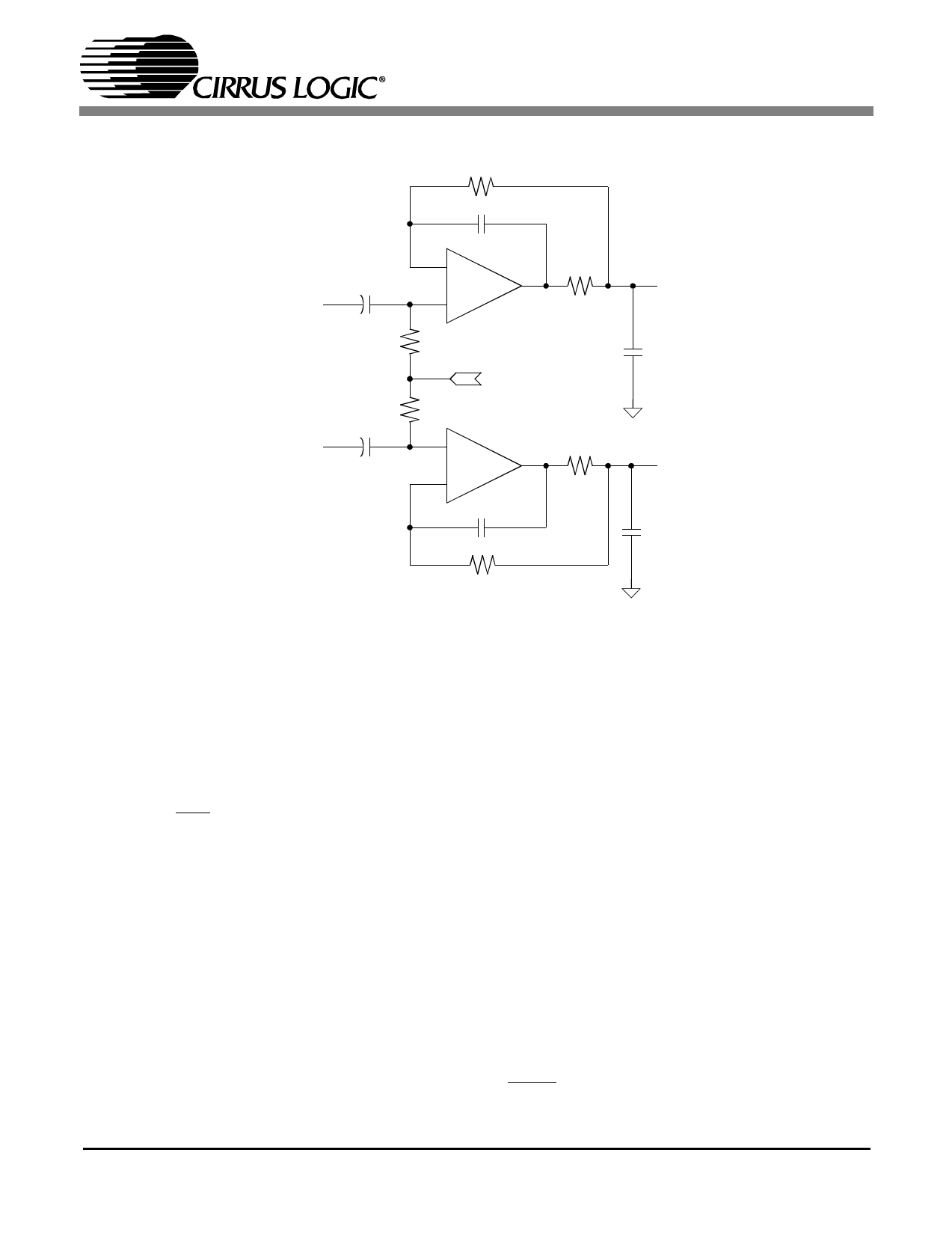
Figure 3. CS5351 Recommended Analog Input Buffer
3.5 High Pass Filter and DC Offset Calibration
The operational amplifiers in the input circuitry driving the CS5351 may generate a small DC offset into
the A/D converter. The CS5351 includes a high pass filter after the decimator to remove any DC offset
which could result in recording a DC level, possibly yielding "clicks" when switching between devices in
a multichannel system.
The high pass filter continuously subtracts a measure of the DC offset from the output of the decimation
filter. If the HPF pin is taken high during normal operation, the current value of the DC offset register is
frozen and this DC offset will continue to be subtracted from the conversion result. This feature makes it
possible to perform a system DC offset calibration by:
1) Running the CS5351 with the high pass filter enabled until the filter settles.See the Digital Filter Char-
acteristics for filter settling time.
2) Disabling the high pass filter and freezing the stored DC offset.
A system calibration performed in this way will eliminate offsets anywhere in the signal path between the
calibration point and the CS5351.
3.6 Overflow Detection
The CS5361 includes overflow detection on both the left and right channels. This time multiplexed infor-
mation is presented as open drain, active low on pin 15, OVFL. The OVFL_L and OVFL_R data will go
to a logical low as soon as an overrange condition in either channel is detected. The data will remain low
DS565PP2
9
Share Link: 