TDA3661 Ver la hoja de datos (PDF) - Philips Electronics
Número de pieza
componentes Descripción
Lista de partido
TDA3661 Datasheet PDF : 16 Pages
| |||
Philips Semiconductors
Very low dropout voltage/quiescent current
adjustable voltage regulator
TEST AND APPLICATION INFORMATION
Preliminary specification
TDA3661
handbook, halfpage
VP C1(1)
1 µF
8
1
TDA3661
5
2, 3, 6, 7
R1
75.1 kΩ
R2
24.9 kΩ
MGS581
VREG
C2 = 5 V
10 µF
(1) C1 is optional (to minimize supply noise only).
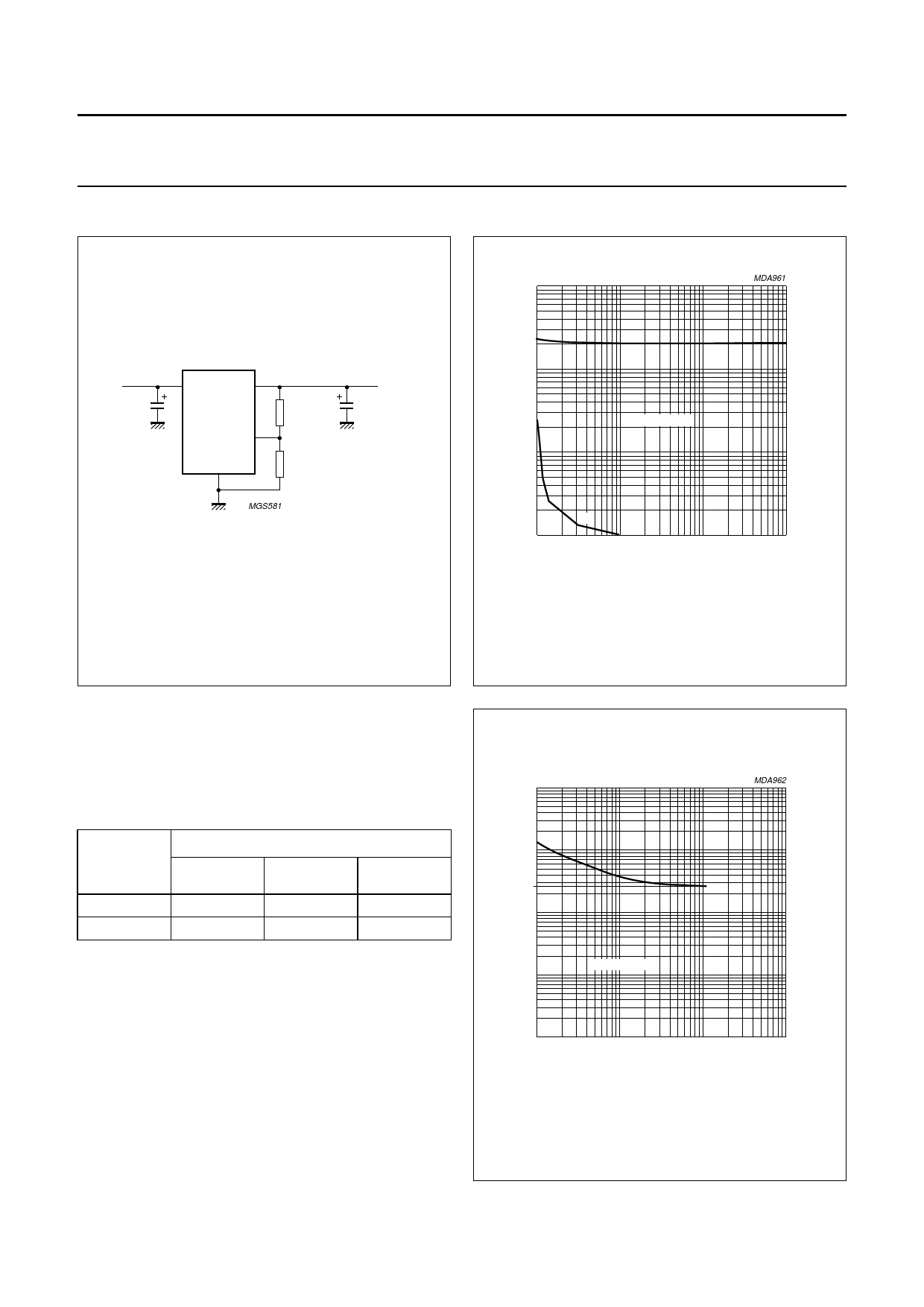
Fig.3 Test circuit.
102
handbook, halfpage
ESR
(Ω)
10
1
MDA961
(1)
stable region
10−1
10−1
(2)
1
10 C2 (µF) 102
(1) Maximum ESR at 200 µA ≤ IREG ≤ 100 mA.
(2) Minimum ESR only when IREG ≤ 200 µA.
Fig.4 Graph for selecting the value of the output
capacitor.
Noise
The output noise is determined by the value of the output
capacitor. The noise figure is measured at a bandwidth of
10 Hz to 100 kHz (see Table 1).
Table 1 Noise figures
OUTPUT
CURRENT
IREG (mA)
0.5
50
NOISE FIGURE (µV)
C2 = 10 µF C2 = 47 µF C2 = 100 µF
550
320
300
650
400
400
Stability
The regulator is stabilized with an external capacitor
connected to the output. The value of this capacitor can be
selected using the diagrams shown in Figs 4 and 5.
The following three examples show the effects of the
stabilization circuit using different values for the output
capacitor.
handbook1, 0h3alfpage
ESR
(Ω)
102
22
10
1
10−1
1
stable region
10
MDA962
102
103
IREG (mA)
Fig.5 ESR as a function of IREG for selecting the
value of the output capacitor.
2000 Feb 01
6
Share Link: 