DS2165 Ver la hoja de datos (PDF) - Dallas Semiconductor -> Maxim Integrated
Número de pieza
componentes Descripción
Lista de partido
DS2165 Datasheet PDF : 17 Pages
| |||
DS2165Q
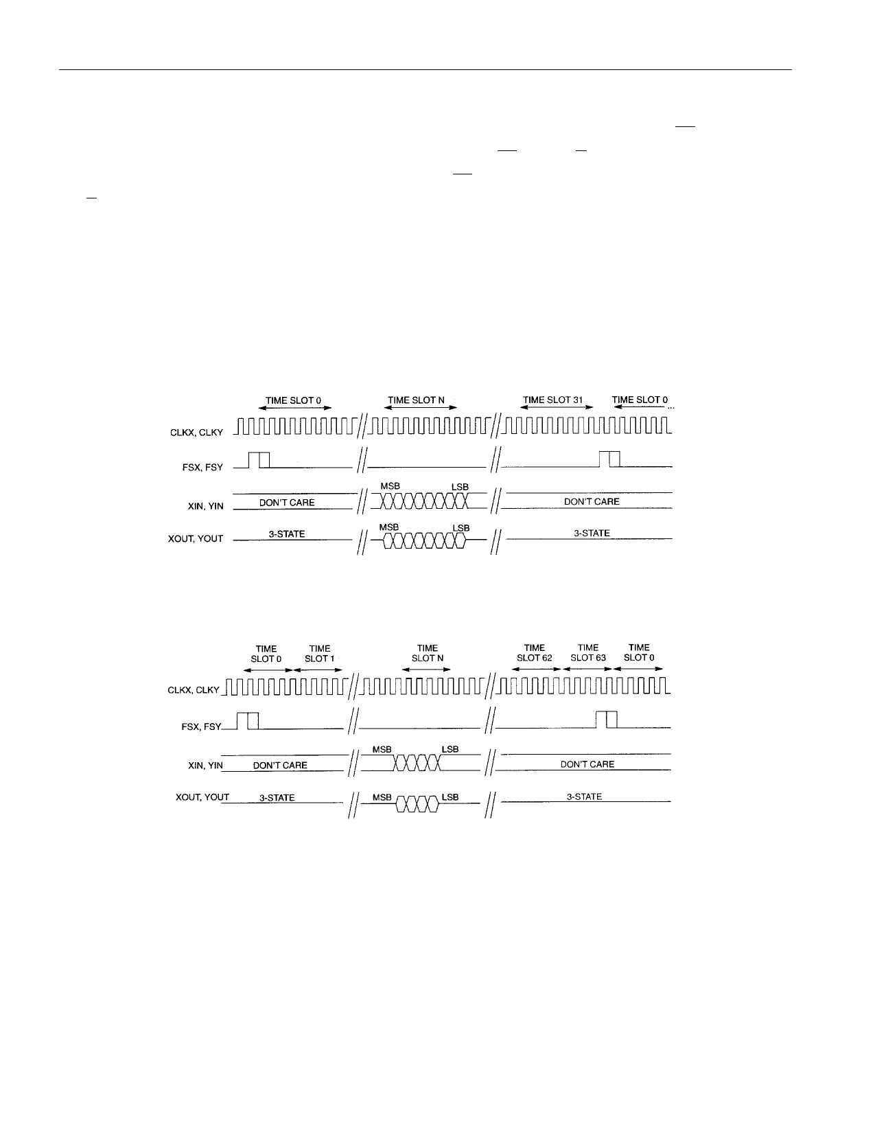
TIME SLOT ASSIGNMENT/ORGANIZATION
On-board counters establish when PCM and ADPCM I/O occur. The counters are programmed by the
time slot registers. Time slot size (number of bits wide) is determined by the state of CP/ EX . The number
of time slots available is determined by the state of both CP/ EX and U/ A (Figures 7 through 10). For
example, if the X channel is set to compress (CP/ EX = 1) and it is set to expect m-law data
(U/ A = 1), then the input port (XIN) is set up for 32 8-bit time slots and the output port (XOUT) is set up
for 64 4-bit time slots. The time slot organization is not dependent on which algorithm has been selected.
Note: Time slots are counted from the frame sync signal starting at the first rising edge of either CLKX
or CLKY after the frame sync.
Figure 7. m-LAW PCM INTERFACE
Figure 8. m-LAW ADPCM INTERFACE
7 of 17
Share Link: 