DS2119M Ver la hoja de datos (PDF) - Dallas Semiconductor -> Maxim Integrated
Número de pieza
componentes Descripción
Lista de partido
DS2119M Datasheet PDF : 9 Pages
| |||
DS2119M
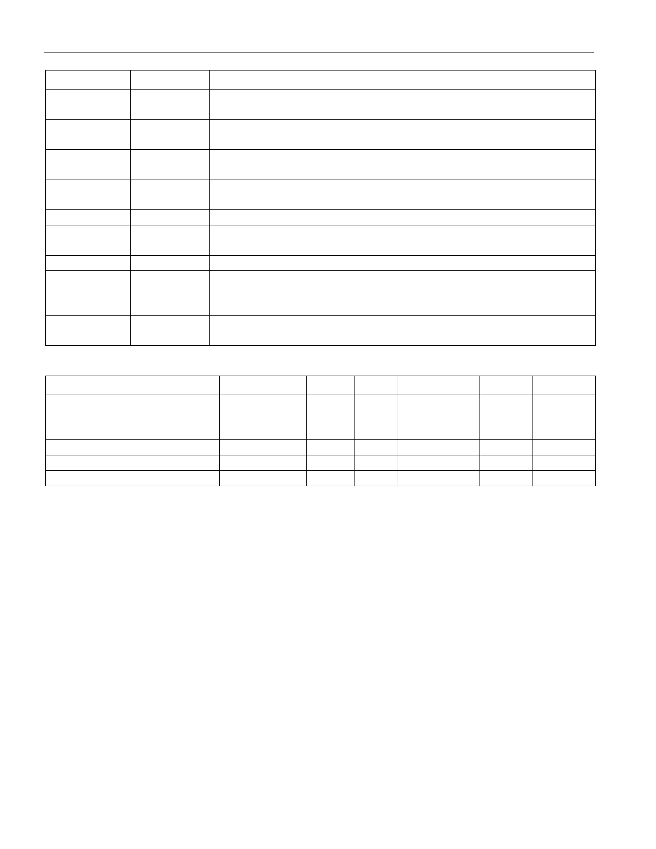
Table 1. PIN DESCRIPTION
PIN
1
2–5, 7–12,
18–21, 23–26
6, 22
13
14
15
16
17
27, 28
SYMBOL
VREF
RxP,
RxN
HS GND
ISO
GND
MSTR/SLV
DIFFSENSE
DIFF_CAP
TPWR
DESCRIPTION
Reference Voltage. 2.85V reference in SE mode and 1.25V reference in
LVD mode; must be decoupled with a 4.7µF cap.
Signal Termination. Connect to SCSI bus signal lines.
Heat Sink Ground. Internally connected to the mounting pad. Should
be grounded.
Isolation. When pulled high, the DS2119M isolates its bus pins (RxP,
RxN) from the SCSI bus.
Ground. Signal ground; 0V.
Master/Slave. Mode-select for the noncontrolling terminator. When
pulled high, MSTR enables the DIFFSENSE driver.
DIFFSENSE. Output to drive the SCSI bus DIFFSENS line.
DIFFSENSE CAPACITOR. Connect a 0.1µF capacitor for
DIFFSENSE filter. Input to detect the type of device (differential or
single-ended) on the SCSI bus.
Termination Power. Connect to the SCSI TERMPWR line and
decouple with a 2.2µF capacitor.
RECOMMENDED OPERATING CONDITIONS
PARAMETER
Termpower Voltage
SE Mode
LVD Mode
Logic 0
Logic 1
Operating Temperature
SYMBOL MIN TYP
VTPWR(SE)
4.0
VTPWR(LVD) 2.7
VIL
-0.3
VIH
2.0
VAMB
0
MAX
5.5
5.5
+0.8
VTPWR + 0.3
70
UNITS
V
V
V
V
°C
NOTES
6 of 9
Share Link: 