E5AN-HAA2HBM-500 Ver la hoja de datos (PDF) - OMRON Corporation
Número de pieza
componentes Descripción
Lista de partido
E5AN-HAA2HBM-500 Datasheet PDF : 16 Pages
| |||
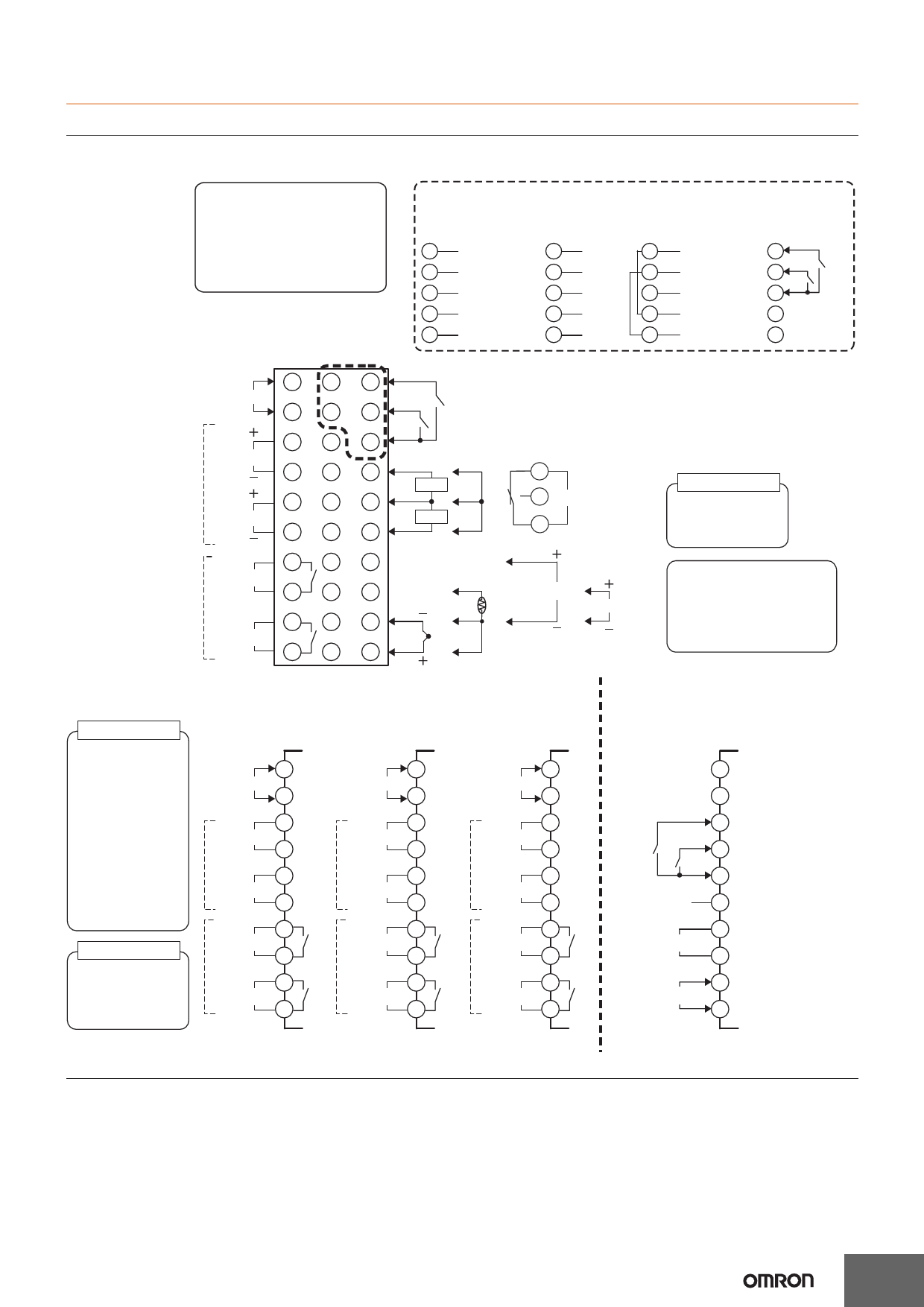
External Connections
Control output 1 and control output 2 are functionally isolated from the internal circuits.
Controllers
Option Units
E5AN-H/E5EN-H
The Temperature Controller is set
for a K-type thermocouple (input
type = 5) by default. An input error
(s.err) will occur if the input type
setting does not agree with the
temperature sensor. Check the
input type.
• 100 to 240 VAC
• 24 VAC/VDC (no polarity)
1
Input power
supply
2
21 11
22 12
3
Control output 1
4
23 13
24 14
5
Control output 2
6
25 15
26 16
7
Auxiliary output 2
8
27 17
28 18
9 29 19
Auxiliary output 1
10 30 20
Communications
E53-EN01
RS-232C
11 SD
E53-EN02
RS-422
11 RDB
12 RD
12 RDA
13 SG
13 SG
21 DO NOT USE 21 SDB
22 DO NOT USE 22 SDA
E53-EN03
RS-485
11 B (+)
12 A (−)
13 DO NOT USE
E53-AKB
Event Inputs
11
12
EV2
EV1
13
21 B (+)
21
22 A (−)
22
Event Inputs
EV2
EV1
CT2
CT1
Potentiometer
O
14
W
15
Auxiliary output 3
CT2
C
16
DO NOT DO NOT
USE
USE
DO NOT A
USE
B
DO NOT V
USE
DO NOT
USE
mA
B
DO NOT DO NOT
USE
USE
Auxiliary output 3
Relay output
SPDT, 250 VAC, 3 A
(resistive load)
A heater burnout alarm, SSR
failure, heater overcurrent
alarm, input alarm, or Remote
SP Input Error is sent to the
output to which the alarm 1
function is assigned.
Control outputs 1, 2
Control Output Unit
Control outputs 1, 2
Refer to page 4
SSR Outputs
75 to 250 VAC, 1 A
(resistive load)
Models with Position-
proportional Control
Relay output
250 VAC, 1 A
(including inrush
current)
Auxiliary outputs 1, 2, 3
Relay output
SPST-NO,
250 VAC, 3 A
(resistive load)
Control Output Unit
1
Input power
supply
2
+
3
Output unit
−4
+
5
Output unit
−6
7
Auxiliary output 2
8
9
Auxiliary output 1
10
SSR Outputs
Models with Position-
proportional Control
Event input/
Transfer output/
Remote SP
1
Input power
supply
2
3
SSR
4
5
SSR
6
7
Auxiliary output 2
8
9
Auxiliary output 1
10
1
Input power
supply
2
3
Open
4
5
Closed
6
7
Auxiliary output 2
8
9
Auxiliary output 1
10
21
22
23
EV3
24
EV4
25
DO NOT USE 26
+
27 4 to 20 mA DC
Transfer output (Load: 600 Ω max.)
28
−
+
29
Remote SP input 4 to 20 mA DC
−
30
Note: Wire all voltage input terminals correctly. The Controller may fail if voltage input terminals are wired incorrectly.
11
Share Link: 