EL2020 Ver la hoja de datos (PDF) - Intersil
Número de pieza
componentes Descripción
Lista de partido
EL2020 Datasheet PDF : 14 Pages
| |||
EL2020
Resistor Value Selection and Optimization
The value of the feedback resistor (and an internal capacitor)
sets the AC dynamics of the EL2020. A nominal value for the
feedback resistor is 1kΩ, which is the value used for
production testing. This value guarantees stability. For a
given gain, the bandwidth may be increased by decreasing
the feedback resistor and, conversely, the bandwidth will be
decreased by increasing the feedback resistor.
Reducing the feedback resistor too much will result in
overshoot and ringing, and eventually oscillations. Increasing
the feedback resistor results in a lower -3dB frequency.
Attenuation at high frequency is limited by a zero in the
closed loop transfer function which results from stray
capacitance between the inverting input and ground.
Power Supplies
The EL2020 may be operated with single or split power
supplies as low as ±3V (6V total) to as high as ±18V (36V
total). The slew rate degrades significantly for supply
voltages less than ±5V (10V total), but the bandwidth only
changes 25% for supplies from ±3V to ±18V. It is not
necessary to use equal value split power supplies, i.e., -5V
and +12V would be excellent for 0V to 1V video signals.
Bypass capacitors from each supply pin to a ground plane
are recommended. The EL2020 will not oscillate even with
minimal bypassing, however, the supply will ring excessively
with inadequate capacitance. To eliminate supply ringing and
the errors it might cause, a 4.7µF tantalum capacitor with
short leads is recommended for both supplies. Inadequate
supply bypassing can also result in lower slew rate and
longer settling times.
NON-INVERTING AMPLIFIER
EL2020 TYPICAL NON-INVERTING AMPLIFIER
CHARACTERISTICS
10V SETTLING
TIME
AV
RF
RG BANDWIDTH 1%
0.1%
+1
820Ω None
50MHz
50ns 90ns
+2
750Ω 750Ω
50MHz
50ns 100ns
+5
680Ω 170Ω
50MHz
50ns 200ns
+10 680Ω
76Ω
30MHz
55ns 280ns
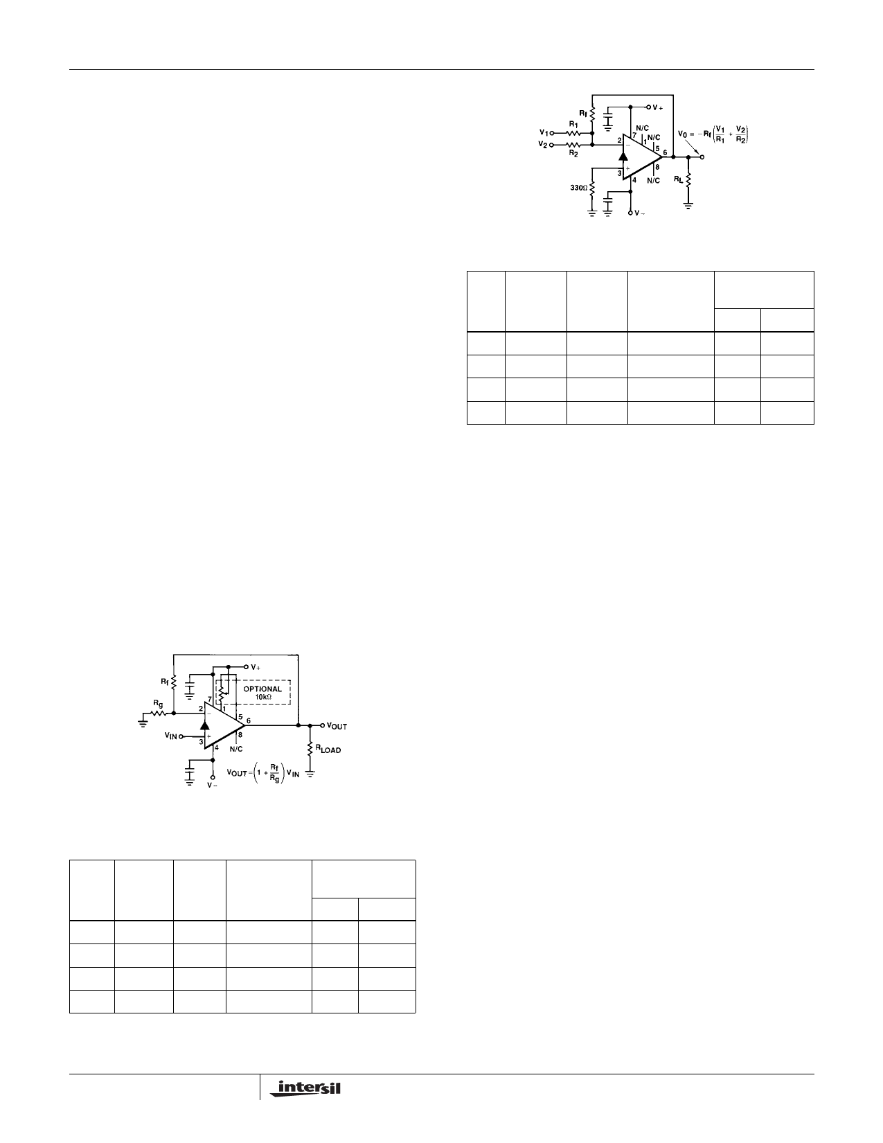
SUMMING AMPLIFIER
EL2020 TYPICAL INVERTING AMPLIFIER CHARACTERISTICS
10V SETTLING
TIME
AV
RF
R1, R2 BANDWIDTH 1%
0.1%
-1
750Ω
750Ω
40MHz
50ns 130ns
-2
750Ω
375Ω
40MHz
55ns 160ns
-5
680Ω
130Ω
40MHz
55ns 160ns
-10 680Ω
68Ω
3MHz
70ns 170ns
Input Range
The non-inverting input to the EL2020 looks like a high
resistance in parallel with a few picofarads in addition to a
DC bias current. The input characteristics change very little
with output loading, even when the amplifier is in current
limit.
The input characteristics also change when the input voltage
exceeds either supply by 0.5V. This happens because the
input transistor's base-collector junctions forward bias. If the
input exceeds the supply by LESS than 0.5V and then
returns to the normal input range, the output will recover in
less than 10ns. However if the input exceeds the supply by
MORE than 0.5V, the recovery time can be 100s of
nanoseconds. For this reason it is recommended that
Schottky diode clamps from input to supply be used if a fast
recovery from large input overloads is required.
Source Impedance
The EL2020 is fairly tolerant of variations in source
impedances. Capacitive sources cause no problems at all,
resistive sources up to 100kΩ present no problems as long
as care is used in board layout to minimize output to input
coupling. Inductive sources may cause oscillations; a 1kΩ
resistor in series with the input lead will usually eliminate
problems without sacrificing too much speed.
9
Share Link: 