EMC1203-ACZL-TR Ver la hoja de datos (PDF) - SMSC -> Microchip
Número de pieza
componentes Descripción
Lista de partido
EMC1203-ACZL-TR
SMSC -> Microchip

EMC1203-ACZL-TR Datasheet PDF : 10 Pages
| |||
Triple/Quad Single-Wire Temp Sensor in MSOP-8 Using SMSC BudgetBusTM Sensor Interface
Datasheet
either be a CPU substrate diode or a regular thermal diode-connected transistor. External diodes at
DP2/DN3 and DN2/DP3 have to be connected in an anti-parallel fashion. Because of this, one diode
will be forward biased while the other is reverse biased and therefore it is recommended to connect
only discrete thermal diodes to these pins.
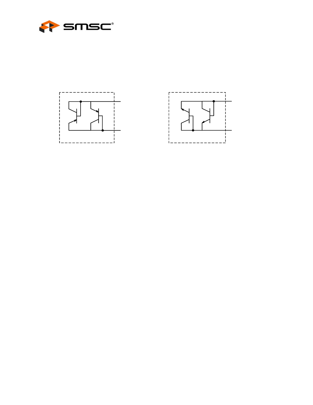
Do not use the anti-parallel interface (DP2/DN3 and DN2/DP3) to connect substrate transistors
(sometimes called thermal diodes or on-chip sense junctions). External diode connected transistors
examples are shown in Figure 3.4
to DP2/DN3
to DN2/DP3
to DP2/DN3
to DN2/DP3
3.2
3.3
Typical remote
discrete PNP transistor
i.e. 2N3906
Typical remote
discrete NPN transistor
i.e. 2N3904
Figure 3.4 EMC1204 External Diode Examples
SMSC BudgetBus™ Sensor Interface
The EMC1203 and EMC1204 series of temperature monitors communicate with a host controller, such
as the KBC1100, through the SMSC BudgetBus™ Sensor Interface. The BBUS is a single wire serial
communication protocol between the computer host and its peripheral devices. Please refer to the
SMSC BudgetBus™ Sensor Interface Specification for detailed information about the modes of
operation.
Power Modes
The EMC1203 and EMC1204 have two basic modes of operation:
Standby Mode:
The host can initiate standby mode by actively pulling the BBUS low. When the Host places the device
in standby mode, the device immediately powers down to draw < 2uA of supply current. It will remain
in this state until it is awakened by the host. If the host pulls the BBUS line low while temperature data
is being clocked out, the device will not enter standby mode until completion of the data transfer. After
entering standby mode, the device will remain in this mode until it is forced into active mode by the
host. The transition from standby to active mode occurs when the host is no longer pulling the BBUS
low.
Active Mode:
The host initiates active mode by enabling a weak pull up on the BBUS. In this mode, the EMC1203
and EMC1204 continuously convert temperature data. During the time that the device is actively
converting a temperature, the BBUS is in tri-state mode, and the Host places a weak pull-up on the
bus to prevent it from floating. After a conversion is completed, the device automatically clocks out the
data from the most recent conversion to the host. When the data packet has been entirely clocked out,
the BBUS returns to tri-state mode, and the ADC begins converting the next temperature sample.
While BBUS is in tri-state mode, the host can command the device to standby mode.
Revision 1.1 (06-11-08)
8
DATASHEET
SMSC EMC1203/EMC1204
Share Link: