FSL126HR Ver la hoja de datos (PDF) - Fairchild Semiconductor
Número de pieza
componentes Descripción
Lista de partido
FSL126HR Datasheet PDF : 13 Pages
| |||
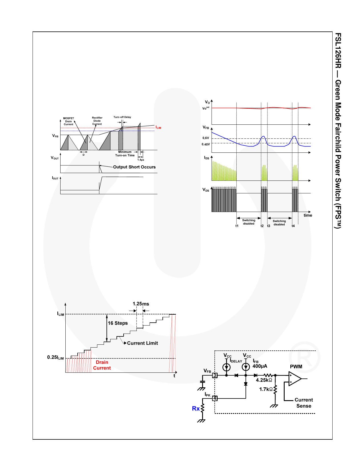
Output-Short Protection (OSP)
If the output is shorted, steep current with extremely
high di/dt can flow through the SenseFET during the
LEB time. Such a steep current brings high-voltage
stress on the drain of SenseFET when turned off. To
protect the device from such an abnormal condition,
OSP detects VFB and SenseFET turn-on time. When the
VFB is higher than 1.6V and the SenseFET turn-on time
is lower than 1.2µs, the FPS recognizes this condition
as an abnormal error and shuts down PWM switching
until VCC reaches VSTART again. An abnormal condition
output is shown in Figure 20.
Switching continues until the feedback voltage drops
below VBURL. At this point, switching stops and the
output voltages start to drop at a rate dependent on the
standby current load. This causes the feedback voltage
to rise. Once it passes VBURH, switching resumes. The
feedback voltage then falls and the process repeats.
Burst mode alternately enables and disables switching
of the SenseFET and reduces switching loss in standby
mode.
Figure 20. Output Short Waveforms (OSP)
Soft-Start
The FPS has an internal soft-start circuit that slowly
increases the feedback voltage, together with the
SenseFET current, after it starts. The typical soft-start
time is 20ms, as shown in Figure 21, where progressive
increments of the SenseFET current are allowed during
the startup phase. The pulse width to the power
switching device is progressively increased to establish
the correct working conditions for transformers,
inductors, and capacitors. The voltage on the output
capacitors is progressively increased with the intention
of smoothly establishing the required output voltage.
Soft-start helps to prevent transformer saturation and
reduce the stress on the secondary diode.
Figure 22. Burst-Mode Operation
Adjusting Peak Current Limit
As shown in Figure 23, a combined 6kΩ internal
resistance is connected to the non-inverting lead on the
PWM comparator. An external resistance of Rx on the
current limit pin forms a parallel resistance with the 6kΩ
when the internal diodes are biased by the main current
source of 400µA. For example, FSL126HR has a typical
SenseFET peak current limit (ILIM) of 1.5A. ILIM can be
adjusted to 1A by inserting Rx between the IPK pin and
the ground. The value of the Rx can be estimated by the
following equations:
1.5A:1A 6kΩ: XkΩ
(1)
X Rx || 6kΩ
(2)
where X is the resistance of the parallel network.
Figure 21. Internal Soft-Start
Burst Operation
To minimize power dissipation in standby mode, the
FPS enters burst mode. As the load decreases, the
feedback voltage decreases. As shown in Figure 22, the
device automatically enters burst mode when the
feedback voltage drops below VBURH.
© 2011 Fairchild Semiconductor Corporation
FSL126HR • Rev. 1.0.0
Figure 23. Peak Current Limit Adjustment
www.fairchildsemi.com
11
Share Link: 