FU-650SDF-FW1M36 Ver la hoja de datos (PDF) - Mitsumi
Número de pieza
componentes Descripción
Lista de partido
FU-650SDF-FW1M36 Datasheet PDF : 5 Pages
| |||
MAY06 (2/5)
MITSUBISHI (OPTICAL DEVICES)
FU-650SDF-FW1Mxx
1.5 μm CWDM DFB-LD MODULE WITH SINGLEMODE FIBER PIGTAIL
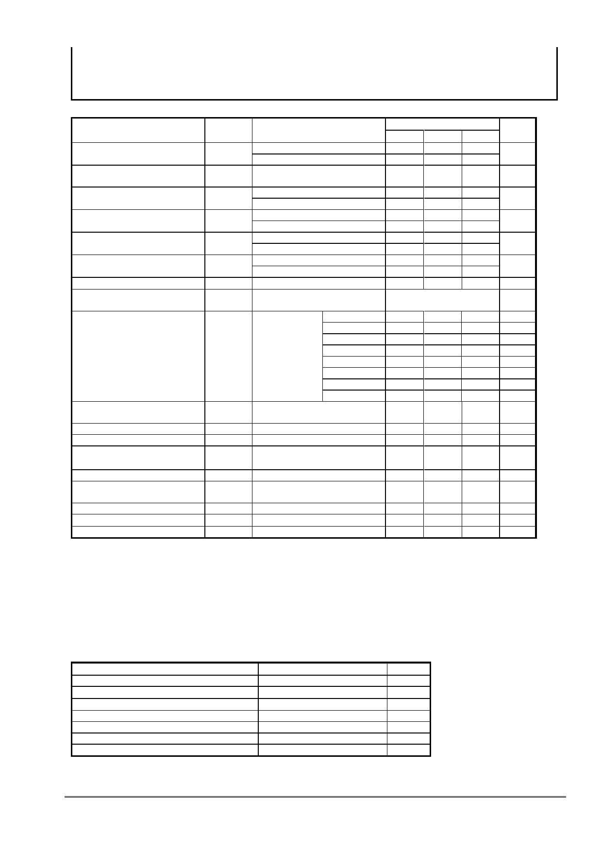
ELECTRICAL/OPTICAL CHARACTERISTICS (Tc= -5~75°C, unless otherwise noted)
Parameter
Symbol
Test Conditions
Limits
Min. Typ.
Threshold current
Ith
CW, Tc=25°C
-
10
CW
2
-
Optical output power
at threshold current
Pth CW, Ibias=Ith
-
-
Operating current
Iop CW, Pf=4mW, Tc=25°C
-
35
CW, APC (Note 1), Tc=75°C
-
60
Operating voltage
Vop CW, Pf=4mW, Tc=25°C
-
1.2
CW, APC, Tc=75°C
-
1.6
Modulation Current (Iop-Ith)
Imod CW, Pf=4mW, Tc=25°C
20
30
(Note 2)
CW, APC
10
-
Deferential Efficiency
η
CW, Pf=4mW, Tc=25°C
0.1 0.13
CW, APC
0.05
-
Differential impedance
Rs -
3
6
Optical output power from
Pf
CW, nominal
4
fiber end
Light-emission central
wavelength
λc
CW, APC
-FW1Mx2
-FW1Mx3
1463
1483
1470
1490
-FW1Mx4
1503 1510
-FW1Mx5
1523 1530
-FW1Mx6
1543 1550
-FW1Mx7
1563 1570
-FW1Mx8
1583 1590
-FW1Mx9
1603 1610
Wavelength temperature
coefficient
λct CW, APC
-
0.1
Side mode suppression ratio
Sr
CW, APC
30
45
Rise and fall time (20~80%)
tr, tf (Note 3) (Note 4)
-
125
Relative intensity noise
Nr
CW, APC, f=1GHz
-
-145
Max.
20
45
100
55
110
1.5
1.7
45
80
-
-
10
1477
1497
1517
1537
1557
1577
1597
1617
0.11
-
150
-130
Unit
mA
μW
mA
V
mA
mA
Ω
mW
nm
nm
nm
nm
nm
nm
nm
nm
nm/°C
dB
psec
dB/Hz
Tracking error (Note 5)
Monitor current
Optical isolation
Dark current (PD)
Capacitance (PD)
Er
Imon
Iso
Id
Ct
CW, APC
CW, Pf=4mW, Vrd=5V,
Tc=25°C
-
Vrd=5V
Vrd=5V, f=1MHz
-
0.5 1.25 dB
0.1
-
2
mA
16
-
-
dB
-
-
0.1
μA
-
-
10
pF
Note 1) “APC” represents operating LD by a constant monitor current for Pf=4mW at Tc=25°C.
Note 2) Modulation current for LD driver shall be less than this “Imod” when the optical extinction ratio is
set around 10dB.
Note 3) 2.48832Gb/s NRZ, 223-1, Pf_ave=2mW, Ibias=Ith, optical return loss from the line should be
greater than 24dB in order to ensure the specified performance.
Note 4) Guaranteed only when the length of LD pins are shorter than 5mm.
Note 5) Er=max|10×log(Pf / Pf@25°C)|
FIBER PIGTAIL SPECIFICATIONS
Parameter
Type
Mode field diameter
Cladding diameter
Secondary coating outer diameter
Connector
Optical return loss of connector
Lfiber
Limits
Unit
SM
-
9.5+/-1
μm
125+/-2
μm
0.9+/-0.1
mm
SC/PC
-
40 (min)
dB
1000+/-100
mm
Mitsubishi Electric Corporation reserves the right to make changes to the products or information contained herein
without notice. No liability is assumed as a result of their use or application.
MITSUBISHI CONFIDENTIAL
Share Link: 