HFA3767 Ver la hoja de datos (PDF) - Intersil
Número de pieza
componentes Descripción
Lista de partido
HFA3767 Datasheet PDF : 6 Pages
| |||
HFA3767
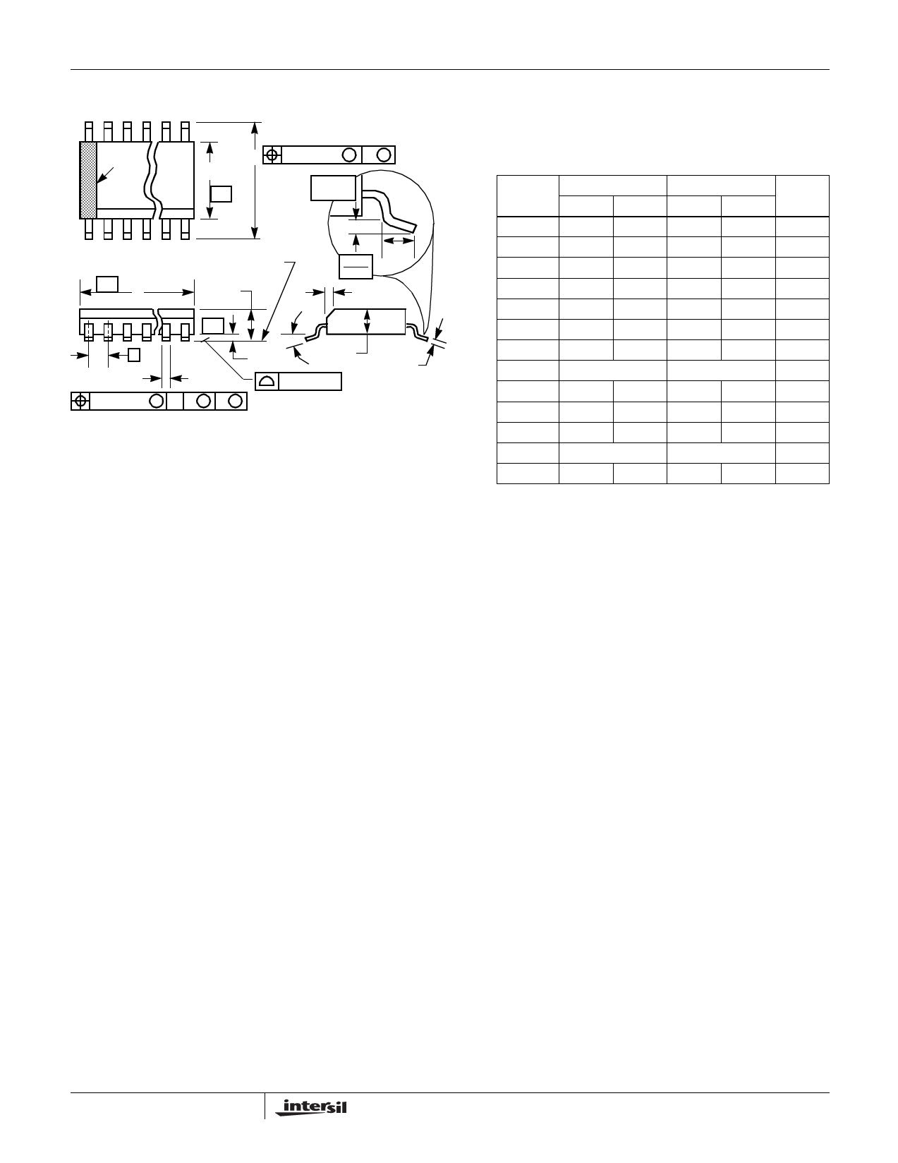
Shrink Small Outline Plastic Packages (SSOP)
N
INDEX
AREA
H
E
-B-
0.25(0.010) M B M
GAUGE
PLANE
123
-A-
D
SEATING PLANE
A
L
0.25
0.010
h x 45o
-C-
α
e
A1
A2
C
B
0.10(0.004)
0.17(0.007) M C A M B S
NOTES:
1. Symbols are defined in the “MO Series Symbol List” in Section 2.2 of
Publication Number 95.
2. Dimensioning and tolerancing per ANSI Y14.5M-1982.
3. Dimension “D” does not include mold flash, protrusions or gate burrs.
Mold flash, protrusion and gate burrs shall not exceed 0.15mm
(0.006 inch) per side.
4. Dimension “E” does not include interlead flash or protrusions. Inter-
lead flash and protrusions shall not exceed 0.25mm (0.010 inch) per
side.
5. The chamfer on the body is optional. If it is not present, a visual index
feature must be located within the crosshatched area.
6. “L” is the length of terminal for soldering to a substrate.
7. “N” is the number of terminal positions.
8. Terminal numbers are shown for reference only.
9. Dimension “B” does not include dambar protrusion. Allowable dam-
bar protrusion shall be 0.10mm (0.004 inch) total in excess of “B” di-
mension at maximum material condition.
10. Controlling dimension: INCHES. Converted millimeter dimensions
are not necessarily exact.
M20.15
20 LEAD SHRINK NARROW BODY SMALL OUTLINE
PLASTIC PACKAGE
INCHES
MILLIMETERS
SYMBOL MIN
MAX
MIN
MAX NOTES
A
0.053 0.069 1.35
1.75
-
A1
0.004 0.010 0.10
0.25
-
A2
-
0.061
-
1.54
-
B
0.008 0.012 0.20
0.30
9
C
0.007 0.010 0.18
0.25
-
D
0.337 0.344 8.56
8.74
3
E
0.150 0.157 3.81
3.98
4
e
0.025 BSC
0.635 BSC
-
H
0.228 0.244 5.80
6.19
-
h
0.0099 0.0196 0.26
0.49
5
L
0.016 0.050 0.41
1.27
6
N
20
20
7
α
0o
8o
0o
8o
-
Rev. 0 5/96
6
Share Link: 