ICS9248YF-150-T Ver la hoja de datos (PDF) - Integrated Circuit Systems
Número de pieza
componentes Descripción
Lista de partido
ICS9248YF-150-T Datasheet PDF : 10 Pages
| |||
ICS9248-150
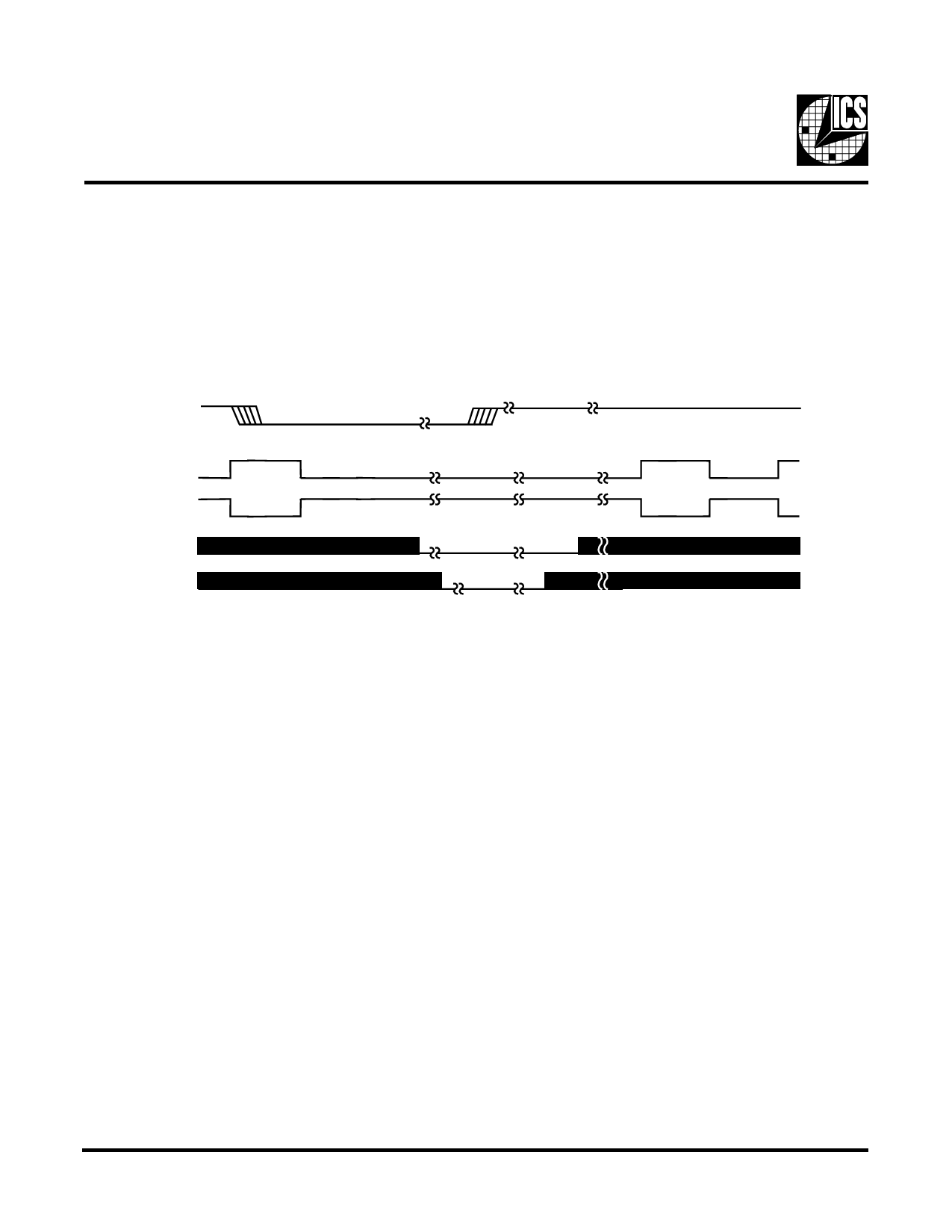
PD# Timing Diagram
The power down selection is used to put the part into a very low power state without turning off the power to the part. PD# is
an asynchronous active low input. This signal needs to be synchronized internal to the device prior to powering down the clock
synthesizer.
Internal clocks are not running after the device is put in power down. When PD# is active low all clocks need to be driven to a
low value and held prior to turning off the VCOs and crystal. The power up latency needs to be less than 3 mS. The power down
latency should be as short as possible but conforming to the sequence requirements shown below.
PD#
CPUCLKT
CPUCLKC
VCO
Crystal
Notes:
1. As shown, the outputs Stop Low on the next falling edge after PD# goes low.
2. PD# is an asynchronous input and metastable conditions may exist. This signal is synchronized inside this part.
3. The shaded sections on the VCO and the Crystal signals indicate an active clock.
Third party brands and names are the property of their respective owners.
8
Share Link: 