IDT7014S Ver la hoja de datos (PDF) - Integrated Device Technology
Número de pieza
componentes Descripción
Lista de partido
IDT7014S Datasheet PDF : 7 Pages
| |||
IDT7014S
HIGH-SPEED 4K x 9 DUAL-PORT STATIC RAM
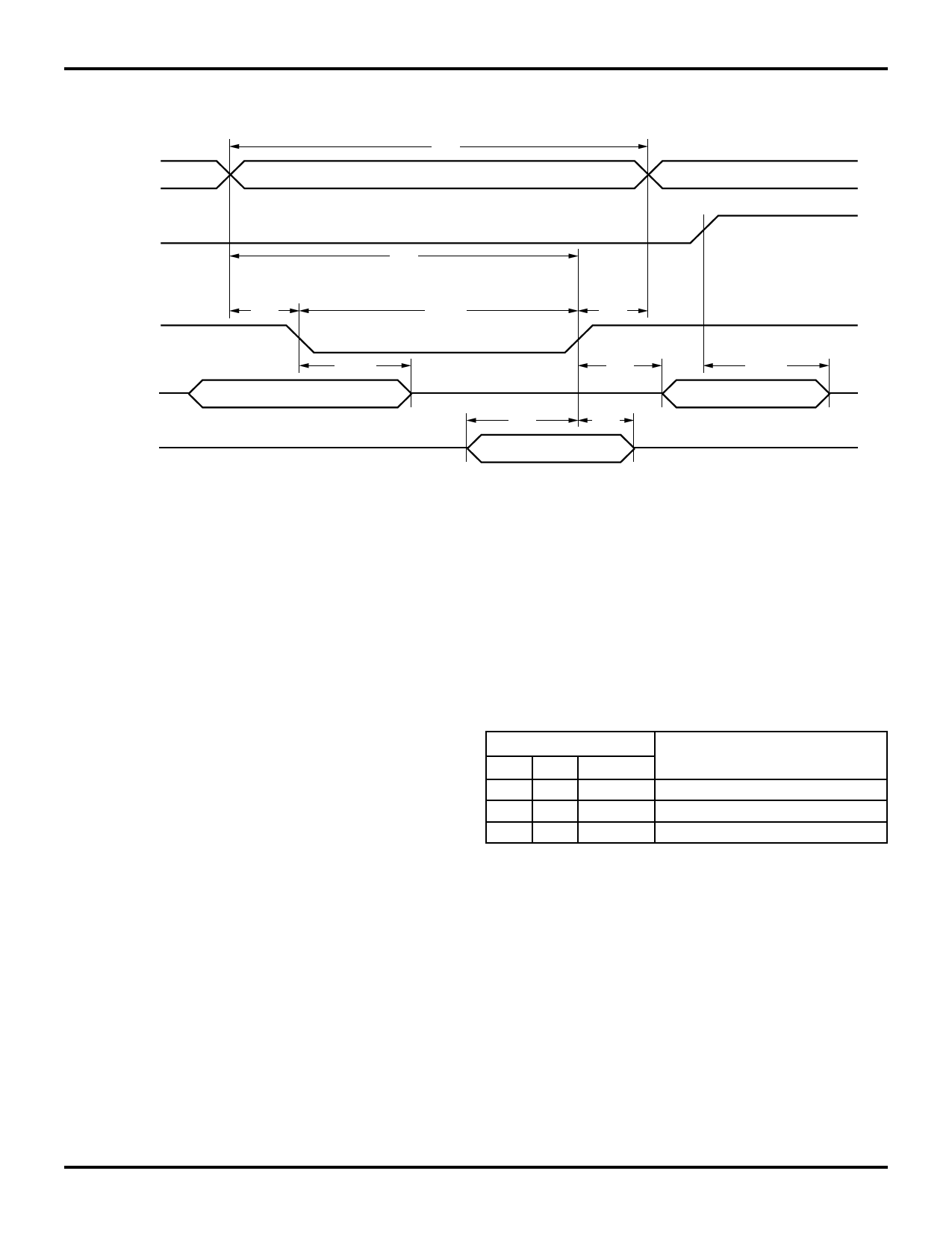
TIMING WAVEFORM OF WRITE CYCLE(1, 2, 3, 4, 5)
MILITARY AND COMMERCIAL TEMPERATURE RANGES
tWC
ADDRESS
OE
tAW
R/W
DATAOUT
DATAIN
tAS
tWZ (4)
(3)
tWP (5)
tDW
tWR
tOW
tDH
tHZ (4)
(3)
2528 drw 10
NOTES:
1. R/W must be HIGH during all address transitions.
2. tWR is measured from R/W going HIGH to the end of write cycle.
3. During this period, the I/O pins are in the output state, and input signals must not be applied.
4. Transition is measured ±200mV from the Low or High-impedance voltage with the Output Test Load (Figure 2).
5. If OE is LOW during a R/W controlled write cycle, the write pulse width must be the larger of tWP or (tWZ + tDW) to allow the I/O drivers to turn off data to
be placed on the bus for the required tDW. If OE is HIGH during an R/W controlled write cycle, this requirement does not apply and the write pulse can
be as short as the specified tWP.
FUNCTIONAL DESCRIPTION
The IDT7014 provides two ports with separate control,
address, and I/O pins that permit independent access for
reads or writes to any location in memory. It lacks the chip
enable feature of most Dual-Ports, thus it operates in active
mode as soon as power is applied. Each port has its own
Output Enable control (OE). In the read mode, the port’s OE
turns on the output drivers when set LOW. The user application
should avoid simultaneous write operations to the same
memory location. There is no on-chip arbitration circuitry to
resolve write priority and partial data from both ports may be
written. READ/WRITE conditions are illustrated in Table 1.
TABLE I – READ/WRITE CONTROL
Left or Right Port(1)
R/W OE
D0-8
Function
L
X
DATAIN Data written into memory
H
L DATAOUT Data in memory output on port
X
H
Z
High-impedance outputs
NOTE:
2528 tbl 10
1. AOL - A11L is not equal to AOR - A11R.
'H' = HIGH,'L' = LOW, 'X' = Don’t Care, and 'Z' = High-impedance.
6.11
6
Share Link: 