IDT72805LB Ver la hoja de datos (PDF) - Integrated Device Technology
Número de pieza
componentes Descripción
Lista de partido
IDT72805LB
Integrated Device Technology

IDT72805LB Datasheet PDF : 26 Pages
| |||
IDT72805LB/72815LB/72825LB/72845LB CMOS Dual SyncFIFOTM
256 x 18, 512 x 18, 1,024 x 18, and 4,096 x 18
COMMERCIAL AND INDUSTRIAL
TEMPERATURE RANGES
on the next LOW-to-HIGH transition of RCLK. The first transition of RCLK will
present the Empty Offset value to the data output lines. The next transition of
RCLK will present the Full offset value. Offset register content can be read out
in the IDT Standard mode only. It cannot be read in the FWFT mode.
SYNCHRONOUS vs ASYNCHRONOUS PROGRAMMABLE FLAG TIM-
ING SELECTION
The IDT72805LB/72815LB/72825LB/72845LB can be configured during
the "Configuration at Reset" cycle described in Table 3 with either asynchronous
or synchronous timing for PAE and PAF flags.
If asynchronous PAE/PAF configuration is selected (as per Table 3), the
PAE is asserted LOW on the LOW-to-HIGH transition of RCLK. PAE is reset
to HIGH on the LOW-to-HIGH transition of WCLK. Similarly, the PAF is
asserted LOW on the LOW-to-HIGH transition of WCLK and PAF is reset
to HIGH on the LOW-to-HIGH transition of RCLK. For detail timing dia-
grams, see Figure 13 for asynchronous PAE timing and Figure 14 for
asynchronous PAF timing.
If synchronous PAE/PAF configuration is selected, the PAE is asserted and
updated on the rising edge of RCLK only and not WCLK. Similarly, PAF is
asserted and updated on the rising edge of WCLK only and not RCLK. For detail
timing diagrams, see Figure 22 for synchronous PAE timing and Figure 23 for
synchronous PAF timing.
REGISTER-BUFFERED FLAG OUTPUT SELECTION
The IDT72805LB/72815LB/72825LB/72845LB can be configured during
the "Configuration at Reset" cycle described in Table 4 with single, double or
triple register-buffered flag output signals. The various combinations available
are described in Table 4 and Table 5. In general, going from single to double
or triple buffered flag outputs removes the possibility of metastable flag indications
on boundary states (i.e, empty or full conditions). The trade-off is the addition
of clock cycle delays for the respective flag to be asserted. Not all combinations
of register-buffered flag outputs are supported. Register-buffered outputs apply
to the Empty Flag and Full Flag only. Partial flags are not effected. Table 4 and
Table 5 summarize the options available.
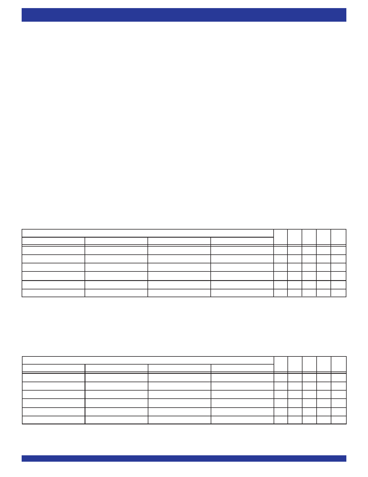
TABLE 1 — STATUS FLAGS FOR IDT STANDARD MODE
Number of Words in FIFO
IDT72805LB
IDT72815LB
IDT72825LB
IDT72845LB
0
0
0
0
1 to n(1)
1 to n(1)
1 to n(1)
1 to n(1)
(n + 1) to 128
(n + 1) to 256
(n + 1) to 512
(n + 1) to 2,048
129 to (256-(m+1))(2)
257 to (512-(m+1))(2)
513 to (1,024-(m+1))(2)
2,049 to (4,096-(m+1))(2)
(256-m) to 255
(512-m) to 511
(1,024-m) to 1,023
(4,096-m) to 4,095
256
512
1,024
NOTES:
1. n = Empty offset (Default Values : IDT72805LB n=31, IDT72815LB n = 63, IDT72825LB/72845LB n = 127)
2. m = Full offset (Default Values : IDT72805LB m=31, IDT72815LB m = 63, IDT72825LB/72845LB m = 127)
4,096
FF PAF HF PAE EF
HHH L L
HHH LH
HHHHH
HH LHH
H L LHH
L L LHH
TABLE 2 — STATUS FLAGS FOR FWFT MODE
Number of Words in FIFO
IDT72805LB
IDT72815LB
IDT72825LB
IDT72845LB
0
0
0
0
1 to (n + 1)(1)
1 to (n + 1)(1)
1 to (n + 1)(1)
1 to (n + 1)(1)
(n + 2) to 129
(n + 2) to 257
(n + 2) to 513
(n + 2) to 2,049
130 to (257-(m+1))(2)
258 to (513-(m+1))(2)
514 to (1,025-(m+1))(2)
2,050 to (4,097-(m+1))(2)
(257-m) to 256
(513-m) to 512
(1,025-m) to 1,024
(4,097-m) to 4,096
257
513
1,025
NOTES:
1. n = Empty offset (Default Values : IDT72805LB n = 31, IDT72815LB n = 63, IDT72825LB/72845LB n = 127)
2. m = Full Offset (Default Values : IDT72805LB m = 31, IDT72815LB m = 63, IDT72825LB/72845LB m = 127)
4,097
IR PAF HF PAE OR
LHH LH
LHH L L
LHHH L
LH LH L
L L LH L
H L LH L
8
Share Link: