IEC-EN60950-1 Ver la hoja de datos (PDF) - Littelfuse, Inc
Número de pieza
componentes Descripción
Lista de partido
IEC-EN60950-1
Littelfuse, Inc

IEC-EN60950-1 Datasheet PDF : 8 Pages
| |||
Application Note:
Use of Low Resistivity Surface Mount PPTC
in Li-ion Polymer Battery Packs
1. Short-Circuit tests and Forced Discharge tests:
These tests are conducted by discharging the
battery with a low resistance load and then allowing
the battery to protect itself or fail by re or
explosion; the latter being a test failure. A test pass
is when battery returns to a safe temperature. Tests
are done at room temperature and elevated
temperatures.
2. Abnormal Charging test, Overcharging test, High
Charging Rate test: These tests are conducted by
subjecting the battery pack to several times more
than the normal charging current or charging at an
abnormally fast rate. When there is a non-resettable
over-current device present, the test is repeated at
a current below which the device activates.
3. Heating and Temperature Cycling tests. These tests
are conducted by raising and cycling the battery
pack to high temperature and then checking to see
if the pack responds safely. Fire, explosion, and
venting would be considered failures.
The purpose of the safety standards is to ensure the
battery pack and cells have protection mechanisms
designed into the overall system to prevent rapid
thermal runaway, re, explosion, rupture, venting, or
even gas bloating of the battery packs. All of these
events can create a hazard to the user or any equip-
ment used with the battery pack.
Typical Li-ion and lithium-polymer battery packs have
several levels of protection in order to meet the
required safety standards and to protect the user and
equipment from battery failure hazards. In addition to
internal cell level protection, external protection
solutions are added to provide further safety mea-
sures. Some battery packs will use what is called a
Battery Management Unit (BMU), which is a small
print circuit board with several protection components
(see Figure 2). The BMU will have a central processing
device, which is usually an IC that controls the battery
charge and monitors the pack for unsafe conditions.
The battery controller IC controls two FETs, which act
as the charge and discharge switches. The battery IC
will turn these FETs off as the primary way to shut
down the battery pack. The IC will use thermistors and
temperature cut-outs (TCO) to sense temperature,
current sense resistors to monitor current, gas gauges
to monitor gas buildup, and fuel gauges to monitor
charge. Upon any unsafe condition, the IC will turn the
FETs off to shut down the pack and stop the fault
event. Because the Li-ion chemistry is so dangerous in
certain conditions, there must be a secondary method
for protection. This secondary protector can be a PPTC
(polymeric positive temperature coef cient) resettable
fuse, thermal fuse, or a controllable battery protector
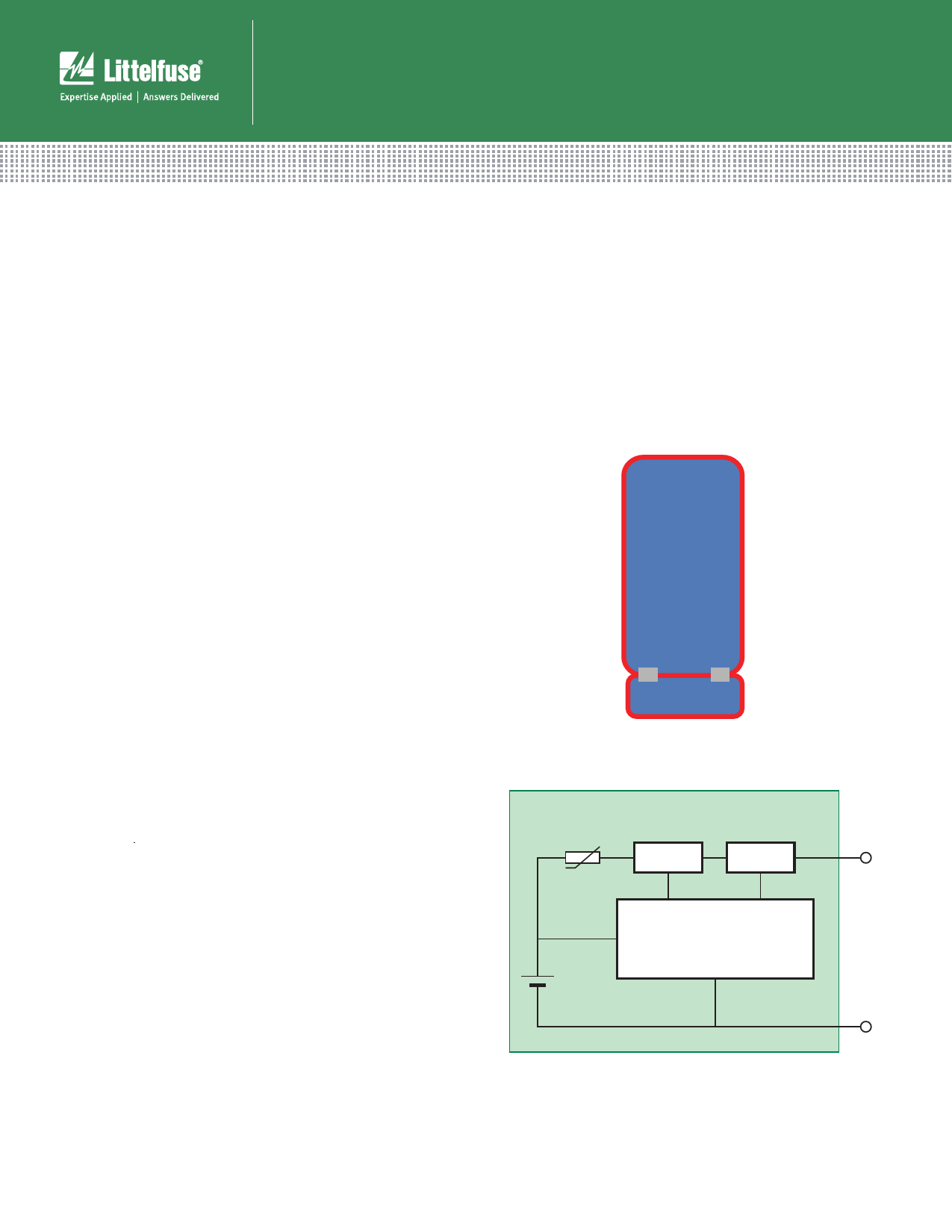
(see Figure 3).
Battery
cell
PCM
Figure 2. A typical Battery Management Unit (BMU) design
Battery Pack
SMD PTC
Switch Switch
+
Discharge Charge
Control IC
Battery
Cell
–
Figure 3. A secondary method of battery protection
©2012 Littelfuse, Inc
3
Share Link: